Two of the most common acid gases produced by the refining industry are chloride compounds such as hydrogen chloride (HCl) and chlorine (Cl2). These compounds can react with water to form solutions of hypochlorous and hydrochloric acid. Droplets that condense are often highly concentrated, and acid concentrations in excess of 10% can be expected.1
A common source of these gaseous compounds is the overhead exhaust/vent of the regeneration tower within a continuous catalytic reforming (CCR) unit. Chloride compounds in the regenerator vent gas are absorbed in 1 wt.% caustic (NaOH) by subsequent contact in a venturi scrubber, before venting chloride-free gas to atmosphere through a wash tower.
 principle of operation.") In Figure 1, the venturi scrubber shows the gas stream as it enters the converging section and the gas velocity increases as the area decreases. At the throat, liquid (caustic) is introduced. In other words, the inlet gas is forced to flow at very high velocity through the small throat section.
In Figure 1, the venturi scrubber shows the gas stream as it enters the converging section and the gas velocity increases as the area decreases. At the throat, liquid (caustic) is introduced. In other words, the inlet gas is forced to flow at very high velocity through the small throat section.
Many nickel alloys containing chromium and molybdenum have useful resistance to HCl in all concentrations up to approximately 150 °F (65 °C) and in very dilute acid up to the boiling point. This is true in non-aerated acid in the absence of oxidizing agents.
Alloy N10665 and N10675 are particularly well suited for handling hydrochloric acid at all concentrations and temperatures (including the boiling point), but are attacked if exposed to an oxidizing agent or aerated environments, which can destroy passivity of the alloy and lead to high corrosion rates. Corrosion resistance in these environments increases with molybdenum content. Other resistant alloys, such as alloy UNS N10276, also contain tungsten.
These Ni-Cr-Mo alloys are also very resistant to chloride SCC. Resistance to pitting and crevice corrosion in acid chloride solutions improves with increasing chromium and molybdenum contents.2
Background
 after cutting.")
During operation, after only 18 months, a leak was observed at the venturi scrubber (ejector) of the CCR unit at a refinery (Figure 2). This ejector was used for caustic injection to neutralize
HCl present in the regeneration tower vent gas before sending the vent gas to a wash tower.
Experimental Procedure
The failed pipe segment was subjected to metallurgical examination. This included different tests classified as visual, microstructural, mechanical, and chemical analyses.
Visual Examination

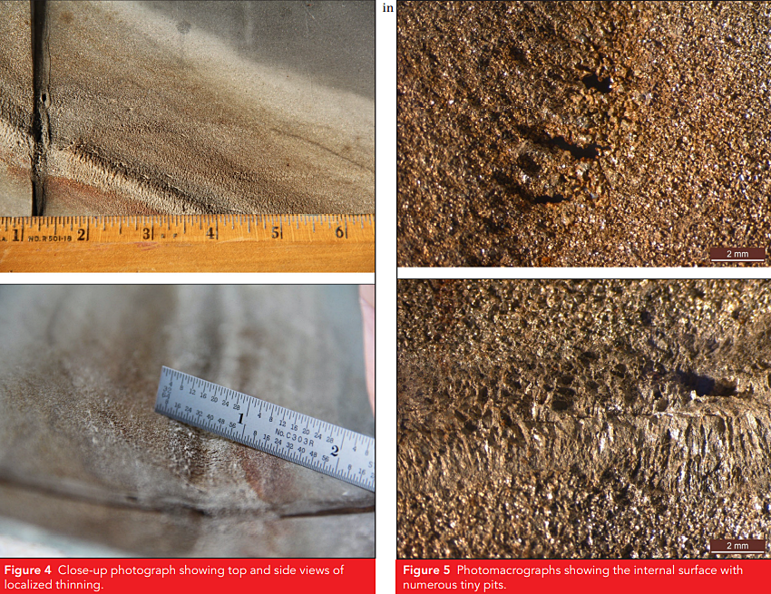
Figure 3 illustrates the venturi scrubber failure and cut sample. Close visual examination of this sample revealed discoloration with liquid patterns. Localized thinning was observed along the liquid patterns. Thickness loss was noticed higher in the upstream side, as shown in Figure 4. Further macro-examination revealed that the thinned area was rough with numerous pits, as shown in Figure 5.
Microscopic Evaluation Examination
The venturi scrubber’s portion was sectioned for metallurgical analysis. A cross section was prepared from the top end with the most severe metal loss. Figure 6 shows the regions of metal removal were highly localized. Additionally, shallow pits were also visible in the metal loss region.
Chemical Examination
Chemical analysis was carried out on the scrubber using optical emission spectroscopy (OES).
Micro-Hardness Examination
Micro-hardness measurements were carried out on the microscopically evaluated sample. The hardness indentation was performed from the ID to OD.
Discussion
Discoloration with liquid patterns was evidence of a premature condensed corrosive HCl water phase (blue) before it was fully neutralized by the incoming NaOH, as illustrated in Figure 7. In addition, reviewing the wash-water history data obtained by a pH online analyzer and lab sampling analysis showed low pH points through the operational history as low as 2.4, which indicated periods of inadequate neutralization.
Moreover, reviewing operating conditions suggested that the equipment was operating close to the HCl dew point of the water rich vent gas at around 130 °F (54 °C). This is considered the typical dew point for HCl in vent gas conditions forming hydrochloric acid droplets.2 Based on the aforementioned evidence collected, it was confirmed the damage mechanism was HCl corrosion.
The venturi scrubber was highly suspected to have dead zones located above the throat at the converging section where a significant amount of HCl in the vent gas can be absorbed into liquid droplets, which caused alloy UNS N06200 to corrode.
This failure mode can be eliminated by preventing the formation of the premature condensation phase prior to neutralization with NaOH solution. This can be achieved by operating well above the HCl acid dew point of 130 °F (54 °C). Also, steam tracing can be evaluated to operate
at higher temperatures. Another remedy is the modification of the venturi scrubber geometry to ensure better mixing of the vent gas with the NaOH.
It is worth highlighting that this type of damage mechanism can affect many materials. Therefore, changing of the metallurgy may improve the life but may not eliminate this failure mode.3-5 Alloy UNS N10276 is another nickel alloy that is commonly used in HCl service. It has excellent corrosion resistance in all HCl concentrations. For example, its resistance surpasses that of alloy UNS N10665 at concentrations under 10%.
In addition, corrosion is definitely less than that of alloy N10665 with existing oxygen and
strong oxidizing agents, which accelerates corrosion.2 Furthermore, studies have shown that alloy UNS N06200 is more corrosion resistant than N10276 in HCl environments.6
References
1 W. Cox, W. Huijbregts, R. Leferink, “Components Susceptible to Dew-Point Corrosion,” in ASM Handbook: Corrosion: Environments and Industries, Vol. 13C, eds. S.D. Cramer, B.S. Covino Jr. (Materials Park, OH: ASM, 2006), pp. 491-496.
2 J.R. Crum, “Corrosion by
Hydrogen Chloride and Hydrochloric Acid,” ASM Handbook: Corrosion: Environments
and Industries, Vol. 13C,
eds. S.D. Cramer, B.S. Covino Jr. (Materials Park, OH: ASM International,
2006), pp. 682-689.
3 API 1RP 571(2011),
“Damage Mechanisms Affecting Fixed Equipment in the Refining Industry”
(Washington, DC: API, 2011).
4 Paul Crook, “Corrosion of
Nickel and Nickel-Base Alloys,” ASM Handbook: Corrosion: Environments
and Industries, Vol. 13C,
eds. S.D. Cramer, B.S. Covino Jr. (Materials Park, OH: ASM International,
2006), pp. 228-251.
5 W.J. Neill, “Use of High
Nickel Alloys in the Petroleum Refining Industry,” CORROSION 2001 (Houston, TX:
NACE International, 2001).
6 L.D. Paul, D.A. Kingseed,
L. Van Gansbeke, “Experience With the New Ni-Cr-Mo Alloy UNS N06200 in Flue Gas
Desulfurization (FGD) Systems,” CORROSION 2000 (Houston, TX: NACE, 2000).