Hydrostatic testing of pipelines is critical during construction and maintenance. It is an important pre-commission test and quality assurance/quality control tool that validates pipeline integrity prior to actual service with flammable fluids at high pressures. It ensures that the required tensile strength can sustain the operating pressure, and that the welds are defect free. In this case study, metallurgical analysis was performed on a carbon steel pipeline that leaked during hydrotesting. Inspection indicated the presence of a defect at the electric resistance welded seam. It was confirmed that the defect was formed due to incomplete fusion during welding.
Hydrotesting and the resulting corrosion problems have been well documented in the past, leading to a sharper focus on the quality of water used for such tests, as well as the post-test operations.1 Hydrotesting can expose any anomalies present in the pipe that may fail at or just above the operating pressure. In most situations, hydrotesting provides a successful result.
A pipe that has no failure demonstrates that it is safe to operate at the maximum operating pressure or maximum allowable operating pressure (MOP/MAOP), while one with a failure identifies defects that would have likely failed in operation and caused costly downtimes. Figure 1 (top) shows a photograph of a hydrotest failure of a 305-mm (12-in), 6.4-mm (0.25-in) wall thickness, API 5L X60 electric resistance welded (ERW) pipe.
Material failures account for up to 25% of pipeline failures in oil and gas operations.2-3 Pipelines are inspected for welding defects using a variety of techniques, such as radiographic testing, ultrasonic testing (UT), magnetic testing, and penetrant testing.4-6 Axial defects, such as those occurring along seam welds, have the lowest safety factors7 and cause pipeline failures in the field.8
In our case study, we highlight the importance of ensuring quality control of the manufacturing processes during pipeline fabrication. This work will add to the metallurgy side of hydrotesting operations, and emphasize the role played by hydrotesting in assessing the integrity of a pipeline prior to installation.
We evaluated a long seam weld defect that was detected during hydrostatic testing of a repaired 508-mm (20-in) natural gas pipeline at a client site. The ERW pipeline was reported to be API 5L X65 PSL2 steel with a nominal wall thickness of 9.53 mm (0.375 in). This pipeline was new, likely manufactured in 2018, and installed in 2019.
Dye penetrant testing, x-ray radiography, and phased array UT inspection all indicated the presence of a lack of fusion (LOF) defect at the ERW seam.
Laboratory Results
Visual Examination
A six-foot section of the pipe containing the defect was sent to our lab for analysis. Pipe dimensions were recorded, and magnetic particle inspection (MPI) was performed prior to sectioning for further destructive analyses. The leak was located about 75 mm (3 in) from the girth weld, as shown in Figure 2.
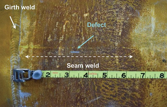
The pipeline showed no deformation across the length. The outside diameter (OD) at the leak was 509.5 mm (20.06 in), and 508.8 mm (20.03 in) at the other end of the 1.8-m (6-ft) pipe section. Average wall thickness values at this other end was found to be 9.63 mm (0.379 in).
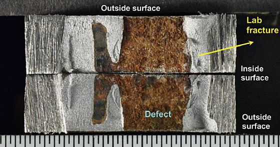
The region containing the defect was sectioned off for metallography and scanning electron microscopy (SEM). The defect area was cleaned, wire brushed on the outside and inside surfaces, and then broken open to expose the defect surfaces.
The two matching surfaces obtained are shown in Figure 3. The defect length was ~7.6 mm (0.3 in) on the outside surface and ~12 mm (0.5 in) on the inside surface.
SEM Examination
SEM and energy dispersive x-ray spectroscopy (EDS) analyses were performed to characterize the defect. One of the matching fracture surfaces was cleaned in Alconox
† to remove the brown corrosion product prior to SEM analysis.
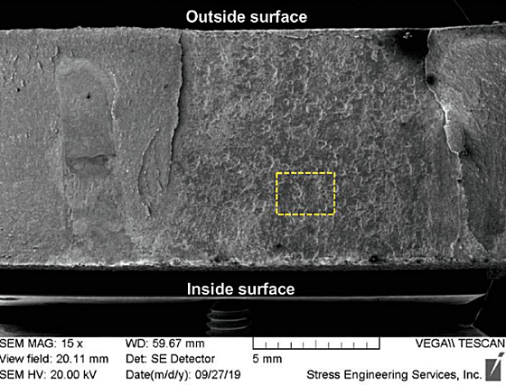
A SEM image of the cleaned half of the defect is shown in Figure 4. Higher magnification images taken in the boxed region indicated several corrosion pits throughout the surface.
EDS analysis was performed on the uncleaned half of the defect. The primary elements present within the brown corrosion product were iron and oxygen, which is expected for atmospheric corrosion of carbon steel. Traces of manganese, silicon, and calcium were also detected.
Metallurgical Examationin
Two cross-sections were prepared for metallography—a matching surfaces mount from the defect region, and the other from an intact region of the seam weld. Figure 5, below, shows a photo-macrograph of the mounted cross-section at the defect region. Higher magnification images taken at the boxed region indicated flow lines from the welding process.
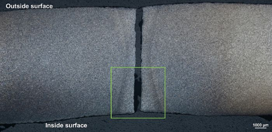
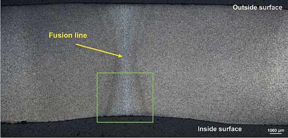
Figure 6 shows a photo-macrograph of the mounted cross-section at the intact weld. Higher magnification images taken at the boxed region indicated the fusion line and f low lines from the welding process.
The differences in general microstructure at the defect region and the intact weld were quite significant. At the defect region, the microstructure was like that of the pipeline base material (i.e., a banded microstructure of ferrite and pearlite). It lacked the expected changes in microstructure that would occur with a complete ERW weld. Incomplete fusion during the welding process resulted in the LOF defect. At the mid-wall region of the intact weld, the microstructure was what would be expected from an API 5L X65 ERW weld (i.e., more ferrite and less pearlite grains).
Vickers microhardness measurements were also recorded across the intact weld mount. The hardness values ranged between 192 and 227 HV, which is well within the 345 HV maximum prescribed by the API 5L (2018) specification.9
Chemical Analysis and Mechanical Testing
Chemical analysis of the pipe base material was performed using optical emission spectroscopy. The measured chemical composition met the specified requirements from API 5L (2018). Tensile and impact testing of the pipeline material indicated that the mechanical properties met the requirements for Grade X65 PSL 2 pipe per API 5L (2018).
Discussion
During hydrotesting, most pipelines fail along the ERW region.10 Lack of fusion or incomplete fusion is quite a common ERW defect.11 It is the failure of the two strip edges to fuse to form a sound weld, most likely as the result of an inappropriate welding procedure. LOF defects could occur at weld edges, mid-wall, or any other geometry. They weaken the seam weld and lead to in-service pipeline failures.12 Although current nondestructive test (NDT) methods have been successful in identifying welding defects, some LOF defects could be virtually undetectable; thereby necessitating the need for hydrotesting.
In this study, a section of the pipeline containing the defect was examined in the lab. MPI analysis as well as visual examination of the fracture surface indicated the presence of a LOF weld defect. The non-fused region was wider on the inside surface (12 mm [0.5 in]) than the outside surface (7.6 mm [0.3 in]). This LOF region also underwent general corrosion, which was confirmed by SEM/EDS analysis.
Metallography performed across the LOF defect, and an intact seam weld brought out differences in microstructure between the two regions. While both mounts displayed f low lines typically observed along the fusion line of the weld, the microstructure at the LOF area was like that of the base material (i.e., banded microstructure of ferrite and pearlite). This indicates incomplete fusion during the welding process, thereby causing an LOF defect to form. The intact weld had an equiaxed microstructure that was appropriate for an API 5L X65 ERW weld.
The pipeline material met the mechanical and chemical property requirements, per API 5L (2018).
Conclusions
The 508-mm (20-in) natural gas pipeline failed the pre-commission hydrostatic testing due to a lack of fusion weld defect at the ERW seam. This was confirmed through visual observations, MPI analysis, SEM/EDS analysis, and metallographic evaluation.
During hydrotesting, most pipelines fail along the ERW region. Lack of fusion occurs due to failure of the two strip edges to fuse completely, thereby weakening the seam weld.
This study reinforces the need for hydrotesting since some lack of fusion weld defects can be undetectable by current NDT techniques.
Source: Stress Engineering, Inc., www.stress.com.
† Trade name.
References and About the Author