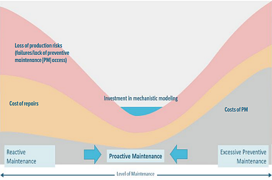
Pipeline integrity management requires corrosion growth rate calculations that must be derived from consecutive external corrosion direct and inline inspections. This conventional approach is based on indirect measurements (structure-to-electrolyte potentials) and post-mortem (excavations, feature mapping) assessments limiting an operator’s capabilities for proactive maintenance in a most cost-effective and timely manner.
With the increasing amount of high-voltage power line corridors, pipeline crossings, and transit systems, interference threats on pipeline assets are more common. This results in a higher risk of accelerated corrosion with poor notification to the pipeline operator, as third-party operational conditions may unexpectedly change.
Advanced mechanistic models calculate in a three-dimensional (3D) environment the cathodic protection (CP) and interference level in a pipeline network. Scientific equations compute the true polarization potential, corrosion rate, and metal loss of the coating defects.
Under time-dependent interference conditions, the calculation of the corrosion growth rate is challenging, as multiple aspects like variations in environmental and system conditions must be considered.
Concept of Mechanistic Modeling
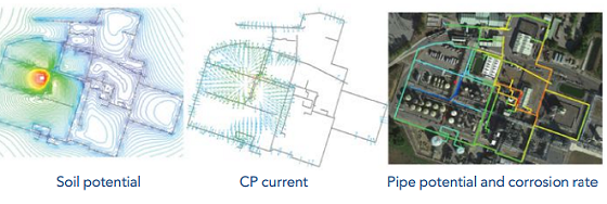
Mechanistic models are based on the well-established physical and electrochemical laws. A physical model of the pipeline network is built based on the geographical coordinates of the girth weld. The soil, coating, and steel properties are attributed to each individual joint of the pipeline. The mechanistic model computes the potential and current distribution from the anode to the pipeline and the induced effect between the power line and pipeline.
In this example, the anode bed is in the middle of a chemical plant. The potential gradient between the positive anode and negative cathode is computed in a 3D space. The current flows perpendicular to the soil potential lines. The coating condition of the pipeline will mainly determine the current and potential distribution. The current received by the pipeline increases its polarization level.
The relationship between the current and polarization level is dictated by the polarization curve, which is soil dependent. The mechanistic model accounts for coating defects of various sizes such that the current density (CD) the coating defect is properly calculated. This is computed for both direct current (DC) and alternating current (AC).
Based on the CD, the corrosion rate and polarized potentials are computed in such a way that the model calculates corrosion rates under CP, AC/DC interference, and a combination thereof.

Replica of Real-World Conditions
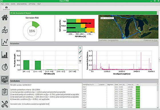
The Elsyca V-PIMS† simulation platform is a boundary element method (BEM)/ finite element method (FEM) based mechanistic modeling software that permits calculating the behavior of cathodically protected pipelines that may be interfered by AC voltage power lines, DC transit systems, and third-party CP systems.
Field information such as structure-to-electrolyte potential measurements at test stations are required to calibrate the model for the real-world conditions. This is typically an iterative process in which simulated current applied potentials are compared with the measured data until alignment is obtained.
The most unknown parameter is the coating resistance. The size (length and width) of the corrosion anomaly obtained from inline inspections (ILI) is used as a first approximation of the percentage of bare steel and thus the coating resistance.
In absence of ILI data or external corrosion features, a blueprint value of the coating resistance is estimated based on the coating type and vintage. Once done, the mechanistic model becomes a replica of the pipeline network and can be considered as its digital twin. Modeling software calculates:
• Current-applied potentials at different soil grade levels
• Polarized potentials at the pipe-to-soil (P/S) interface for any point of the pipeline routing
• AC and DC CD
• AC-induced voltage
• AC and DC line current
• Current through all connections
• Corrosion rate and accumulated metal loss
The simulation results are generated for each individual joint in the model. Field data collected at the test stations lead to computed corrosion rates at and in between the test stations. In other words, mechanistic models compute the corrosion health status for the full coverage of the pipeline network.

Proactive CP Maintenance
Mechanistic models provide direct insight on the impact of external events on the pipeline corrosion status. Changes in the CP behavior and AC/DC interference level are captured during the annual (test stations) and bimonthly (rectifiers) surveys or through remote monitoring devices, and lead to an update of the mechanistic model. Variations in the rectifier output, for example, are provided to the mechanistic model that will recalculate the protection level and corrosion rate on the pipeline network.
Monitoring of the corrosion health status is determined by the sampling frequency of the field data. The most influencing system components ( for example, rectifier with largest coverage) are easily determined the mechanistic model. Through what-if simulations, it is possible to identify the most strategic locations for coupons or corrosion rate probes for monitoring purposes.
Since the full coverage of the pipeline network is calculated, the amount of test stations can be strongly reduced. Upgrading the CP or AC/DC mitigation systems is not a trial-and-error exercise, but system modifications are justified by modeling them upfront prior to putting any boots on the ground. A good balance is reached between required inspections (location and time) and predicted risk.

Monitoring and Risk-Based Inspection Strategies
Mechanistic models support pipeline operators in the decision-making process with respect to corrosion assessment and prevention. Pipeline integrity management requires corrosion growth rate calculations that currently must be derived from consecutive external corrosion direct assessments and ILI.
The conventional approach is based on indirect measurements (potentials) and post-mortem (excavations, feature mapping) assessments limiting the operator’s capabilities for proactive maintenance in a most cost-effective and timely way. Enbridge Pipeline Inc. has initiated an integrated external corrosion management program supported by mechanistic models.
In a first step the as-is CP level and corrosion rate are calculated based on the latest survey data. Hot spots in the pipeline network are identified, which lead to a first intervention. This can be in the form of additional field inspections for model validation or the implementation of countermeasures that are elaborated in the model.
Secondly, historical survey data are utilized to rerun the models and compute the seasonal (environmental) and system variations. For each simulation, the corrosion rate and metal loss are obtained. The time interval between the field data is multiplied by the corrosion rate and accumulated metal loss or corrosion growth rate is obtained. Based on the variations in corrosion rates, a more intelligent integrated inspection approach is obtained.
Sources: Elsyca, www.elsyca.com; Enbridge, www.enbridge.com.
Disclaimer and About the Authors † Trade name.