Carbon dioxide (CO2) is routinely encountered in oil and gas production. Much research has been done and compiled on this damage mechanism since the 1940s with the nomenclature changing over the years: condensate well corrosion, organic acid corrosion, carbonic acid (H2CO3) corrosion, sweet corrosion, and mesa attack.1
CO2 corrosion depends primarily on three factors: pH (CO2 partial pressure), temperature, and flow rates. At low pH values (<4), high values of uniform corrosion are observed since the siderite (FeCO3) scales are loosely adhered to the surface and are not protective. At higher pH values (>5), corrosion rates were found to be flow dependent and more or less independent of pH. At high pH and high temperatures, the metal surfaces are protected by stable FeCO3 scales.
In the intermediate pH range, the FeCO3 scale is semiprotective, which means localized corrosion is possible. The presence of acetates and acetic acid (CH3COOH) dissolves these protective scales, causing higher corrosion rates. The presence of sulfides, on the other hand, tends to lower corrosion rates because iron sulfide (FeS) scales are more stable than FeCO3. The addition of 0.5 to 1% chromium to the carbon steel (CS) can lead to reduction in mesa corrosion rates.
Proper metallurgy and microstructures also play a role; with normalized steels having a ferritic-pearlitic microstructure providing a better anchor pattern for the protective films compared to quenched and tempered steels that have a martensitic microstructure. Preferential dissolution of ferrite lamellae within pearlite colonies and the anchoring effect of the cementite (Fe3C) layers lead to ease of formation of protective carbonate scales.
Although CO2 corrosion is very commonly observed in oil and gas production environments, surprisingly, most corrosion failures are unreported, especially with mid-size oil and gas companies that may not have a well-developed asset integrity program.2 The two cases illustrated in this article are intended to shed more light on such failures and provide guidance in this regard.
Laboratory Results
One client submitted two perforated fittings, a 51-mm (2-in) tee and a 51-mm pipe nipple, to our lab for metallurgical examination. It was reported that these fittings were operating in comingled service (condensate and produced water). Both leaks occurred at the 6 o’clock position.
Visual Examination
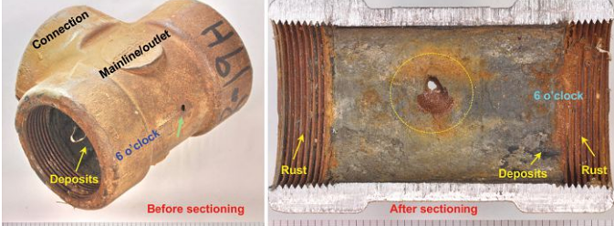
The perforation on the tee (green arrow) was observed adjacent to the forging line, as shown in Figure 1. The tee was sectioned at the 3 and 9 o’clock positions for further examination. The perforation was located on the mainline at the point where the flow path of the connection intersects with the mainline. The inside surface had gray deposits, while the threads had rust-colored deposits (yellow arrows).

The gray deposits appeared denser on the mainline (6 o’clock) than on the connection (12 o’clock). Adjacent to the perforation, the gray deposits were stratified (dotted yellow circle). Reddish brown deposits were also present. Representative gray deposits were collected for further examination. The tee was sectioned through the perforation ( parallel to the threads in the transverse direction) for metallography. Significant material thinning was evident adjacent to the perforation. Based on these visual observations, it is evident that the perforation on the tee occurred due to corrosion/wall loss on the inside surface.

The pipe nipple also had significant material thinning and corrosion, as shown in Figure 2. Mechanical scratches along the length of the fitting were also evident (white arrows). The ends of the fitting had male threads; based on the absence or presence of rust, engaged or unengaged threads were determined, respectively. One of the ends had perforated through the unengaged thread root (green arrow).
The pipe nipple was sectioned at the 3 and 9 o’clock positions for further examination. The inside surface of the fitting had gray and rust-colored deposits (yellow arrows). Significant material thinning was evident at the 6 o’clock position. The perforation was also present close to this position. The pipe nipple was sectioned longitudinally through the perforation for metallography. Based on these visual observations, it is evident that the perforation on the pipe nipple also occurred due to corrosion/wall loss on the inside surface.
Metallography
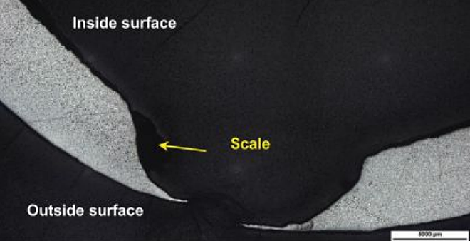
A metallographic cross section was prepared through the perforation on the tee, as shown in Figure 3. The photomicrograph also shows stratified scales present along the corroded surface. The base metal microstructure consisted of the following phases: Widmanstatten ferrite, blocky ferrite, and pearlite.

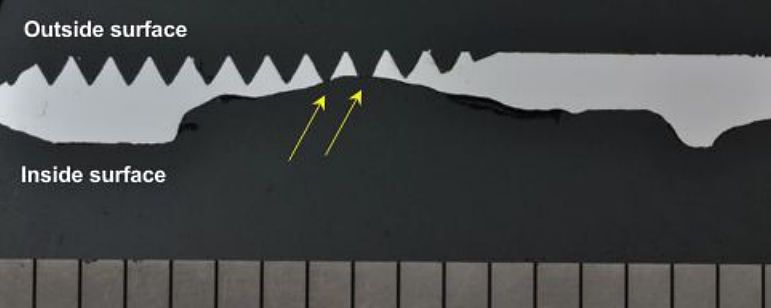
Metallography was also performed through the pipe nipple perforation, as shown in Figure 4. The macro-photograph across the consumed threads indicates that the corrosion had perforated at least two thread roots (yellow arrows). The fitting had a ferrite-pearlite microstructure, which is typical for CS.

Scanning Electron Microscopy and Energy Dispersive X-Ray Spectroscopy Analyses
Scanning electron microscopy (SEM) and energy dispersive x-ray spectroscopy (EDS) dot map analyses of the pit region were performed following sectioning through the perforation on the tee. The stratified corrosion deposits on the inside surface of the tee primarily contained oxygen and iron, with significant traces of carbon, sulfur, and silicon, and minor traces of copper, manganese, sodium, calcium, and chlorine. Similar analyses were performed on the pipe nipple following sectioning through the consumed threads. The pipe nipple corrosion deposits primarily contained oxygen, carbon, and iron, with traces of aluminum, calcium, sulfur, silicon, sodium, barium, and chlorine. The SEM images and EDS dot maps are available in our NACE conference publication.
3
X-Ray Diffraction Analysis
The deposits/corrosion products removed from the inside surface of the tee were analyzed using EDS and x-ray diffraction (XRD). The former method identifies the elements present; the latter identifies crystalline compounds, but does not detect non-crystalline organic sludges. EDS analysis confirmed that the predominant elements present in the deposits were carbon, oxygen, sulfur, and iron.
XRD analysis indicated that the primary crystalline phases present were siderite—52 wt%, quartz (SiO2)—22 wt%, mackinawite (FeS)—7 wt%, greigite (Fe3S4)—11 wt%, troilite (FeS)—3 wt%, and sulfur—5 wt%. Siderite is formed from carbonic acid corrosion (CO2 corrosion) of steel, while mackinawite, greigite, and troilite are iron sulfides formed from hydrogen sulfide (H2S) corrosion of steel.
Similar analyses were performed on the deposits/corrosion products removed from the inside surface of the pipe nipple. EDS analysis confirmed that the predominant elements present in the deposits were carbon, oxygen, barium, sulfur, and iron. XRD analysis indicated that the primary crystalline phases present were barite (BaSO4)—9 wt%, siderite (FeCO3)—21 wt%, mackinawite (FeS)—4 wt%, calcite (CaCO3)—36 wt%, and akaganeite—30 wt%. Siderite and mackinawite are formed during CO2 and H2S corrosion, respectively. Calcite and barite scales typically form from produced water. Akaganeite forms only in environments containing high concentrations of chlorides, such as produced water.
Vickers Hardness Test
Vickers hardness tests were performed on the metallographic mounts taken across the perforations on the tee and the pipe nipple cross sections. The average hardness for the tee was 163.5 HV, which converts to 84 HRB per ASTM A370.4
These hardness values are below the 92 HRB maximum specified for ASTM A2345 Grade WPB fittings. The average hardness for the pipe nipple was 140 HV (77 HRB), which is typical for these CS fittings.
Chemical Analysis
Elemental composition of the tee and pipe nipple determined using optical emission spectroscopy (OES) indicated that the tee material met the requirements for ASTM A234 Grade WPB steel, while the pipe nipple material met the requirements for ASTM A1066 Grade B specification.
Discussion
The corrosion product in the tee was primarily iron carbonate, which is commonly formed during carbonic acid corrosion of steel. The presence of iron sulfides indicates that dissolved H2S also contributed to the corrosion. The presence of greigite is indicative of periodic ingress of oxygen into the system, which can significantly increase the corrosion rate of CS equipment.7
The tee perforation was located at a turbulent zone where the fluid from the connection line intermingled with the fluid from the main line, which led to significant material thinning adjacent to the perforation. The corrosion deposits away from the perforation were of uniform thickness. OES analysis indicated that the tee met the chemical composition requirements for ASTM A234 Grade WPB steel. The microstructure was characterized by Widmanstatten ferrite, blocky ferrite, and pearlite, which is typical of CS. The investigation did not detect any metallurgical defects or deficiencies that could have contributed to the perforation.
The pipe nipple perforation occurred at the root of a thread, which corresponds to a location with the least wall thickness. The corrosion product was primarily iron carbonate, which indicates CO2 corrosion. The presence of iron sulfides indicates that dissolved H2S also contributed to the corrosion. The pipe nipple chemical composition met the requirements for ASTM A106 Grade B steel. The microstructure was characterized by ferrite and pearlite, which is typical of CS. The investigation on the pipe nipple did not detect metallurgical defects or deficiencies that could have contributed to the corrosion damage.
Conclusions
1. The tee perforated due to localized corrosion and fluid turbulence. Corrosion was from carbonic acid and hydrogen sulfide. The deposits contained iron carbonate, and two forms of iron sulfide, one of which (Fe3S4) typically forms in oxygenated environments implying oxygen ingress. The perforation occurred at a location where fluids intermingled and caused turbulent conditions.
2. The pipe nipple corroded at the inside surface due to carbonic acid and hydrogen sulfide. The deposits contained iron carbonate and iron sulfide. The location of the perforation was at a thread root, where the wall thickness is at a minimum.
3. The best mitigation strategies against CO2 corrosion tie back to having robust corrosion control programs, which includes corrosion test coupon installation, monitoring field water chemistry, corrosion inhibitor development and inhibitor residual monitoring, as well as corrosion rate monitoring using ultrasonic or in-line inspection tools.8-9
References and About the Authors