Two cases of chloride stress corrosion cracking (Cl-SCC) of Type 2205 duplex stainless steel (UNS S31803) tubing on a crude tower, and one of sulfide stress cracking (SSC) of Type 2205 duplex stainless steel outlet piping in a hydrocracker are presented. Proper welding practices and process control can mitigate such failures.
Duplex stainless steels (DSS) are becoming common in the refining industry due to their ability to offer both corrosion resistance and mechanical strength. Examples include Type 2205 DSS (UNS S31803) and 3RE60†. Their appeal results from a combination of the ferritic and austenitic microstructures, which can offer an economical solution for many industrial processes. The ferrite phase offers high strength, while the austenite phase offers corrosion resistance. While DSS have existed since the 1930s, issues with design and welding practices limited their widespread application. Improvements in manufacturing processes and welding practices in the 1980s expanded the usage of DSS beyond the scope of their original introduction.1 Today, DSS can be found in many refinery applications that require higher alloys for corrosion resistance.
SCC is traditionally defined as metallurgical failure resulting from the combined exposure of a chemical environment and tensile stress below the yield strength of a susceptible material. Cl-SCC, an anodic damage mechanism occurring in an aqueous chloride environment, is a major corrosion problem that has been repeatedly observed in numerous industries.2-3 DSS are commonly used in services where corrosion-resistant alloys are necessary to prevent attack from such contaminants. SSC is a cathodic damage mechanism occurring under simultaneous exposure to tensile stress, free water, and hydrogen sulfide (H2S), wherein atomic hydrogen penetrates the steel matrix, causing embrittlement— typically in carbon and low-alloy steels. However, SSC of DSS has been reported in refining operations.1
Proper fabrication is a critical factor in achieving the desired corrosion resistance of DSS. Reviews of previous failures have shown that many were the result of factors that include improper welding, heat treatment, or other manufacturing processes.1,4 Improper fabrication practices can result in non-optimal distributions of the austenite and ferrite phases in the microstructure and high hardness in heat-affected zones (HAZ).3-4 These factors can result in decreased corrosion resistance and increased internal material stress, both of which raise the likelihood for SCC. The typical DSS compositions consist of 18 to 30% Cr, 3 to 8% Ni, and 1 to 5% Mo.5
In addition to material fabrication, operating parameters and process components play a large role in the susceptibility of DSS to SCC. While duplex is commonly used as an upgraded alloy to resist corrosive environments, failures are still reported.2 Industry data suggest that critical process factors, such as the operating temperature, chloride concentration, and the susceptibility for deposit formation, are crucial in order to accurately assess the resistance of DSS in a given environment.3
Resistance to corrosion and cracking in chloride-containing environments has made DSS a popular choice in various refinery applications. Heat exchanger tubes manufactured from DSS are commonly found in tower overhead coolers, where chloride levels are relatively high. Duplex SS is common in reactor effluent air coolers as well, where condensation and deposits may promote a unique corrosive environment.1,4
In this article, a few case studies are presented showing DSS failures. The first case history displays Cl-SCC of a finned DSS heat exchanger tube, while the second case illustrates a monoethanolamine (MEA) hydrochloride salt causing fracture in a seamless DSS heat exchanger tube. The third case shows SSC failure of DSS piping occurring as a result of improper fabrication and high hardness. Fabrication and process controls are also defined.
Case Studies on DSS Cracking
Case History 1—Overhead Exchanger Finned Tube Failure in Crude Tower at Refinery A
Following a through-wall failure of an overhead heat exchanger piping on the crude tower, a failure analysis of a finned tube was carried out. The inside diameter (ID) of the tubes was exposed to the overhead vapor (naphtha, water [H2O], H2S, carbon dioxide [CO2], hydrochloric acid [HCl], and ammonia [NH3]). Sampling data and ionic model outputs indicated a moderate risk of ammonium chloride salt formation and a high risk of MEA hydrochloride salt formation in the tower top and overhead line. The crude slate included products that were treated with H2S scavengers that likely contributed to the tramp amine concentration in the tower vapors. Salt formation temperatures for MEA salts were as much as 22.2 C higher than the tower overhead temperature. Overhead chloride concentration ranged from 20 to 50 ppm with MEA concentrations at 8 to 20 ppm and a tower overhead temperature of 121 to 127 °C (250 to 260 °F). The outside diameter (OD) of the tubes (the fins were made of an aluminum alloy) was in contact with ambient air. The results of the lab analysis clearly indicated that aqueous corrosive salts condensing at the 12 o’clock position on the ID of these tubes were directly responsible for the damage to the equipment and eventual failure.
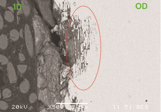
Figure 1 shows an as-received photograph of the finned tube. Localized thinning at the top of the tube is evident, which likely led to the cracking. Scanning electron microscopy (SEM) analysis of a cross section of the crack indicated intergranular attack with multiple crack initiation sites (Figure 2). Energy-dispersive x-ray spectroscopy (EDS) analysis of the ID scale showed the presence of chlorides, which were also detected in the corrosion products in the intergranular attack regions. The base metal was verified to be Type 2205 DSS.
Case History 2—Top Pumparound Exchanger Tube Failure in Crude Tower at Refinery B
A top pumparound (TPA) seamless heat exchanger tube failed, following which a failure analysis was conducted to determine the cause. The OD of the tube was exposed to TPA fluids (hydrocarbons, MEA hydrochloride salt) at 149 °C (300 °F). The ID of the tube was exposed to crude oil as it was a part of the pre-heat train. Sampling data and ionic model outputs indicated a high risk of MEA hydrochloride salt formation in the tower top and overhead line. The crude slate included products that were treated with H2S scavengers that likely contributed to the tramp amine concentration in the tower vapors. Additional failures in this system included corrosion of the pump and piping components, all of which were confirmed to be due to the presence of corrosive salts flowing from the tower draw tray.
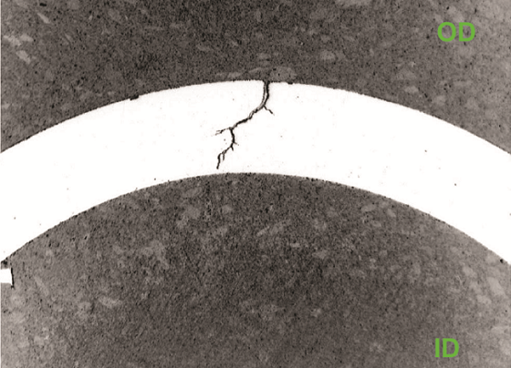
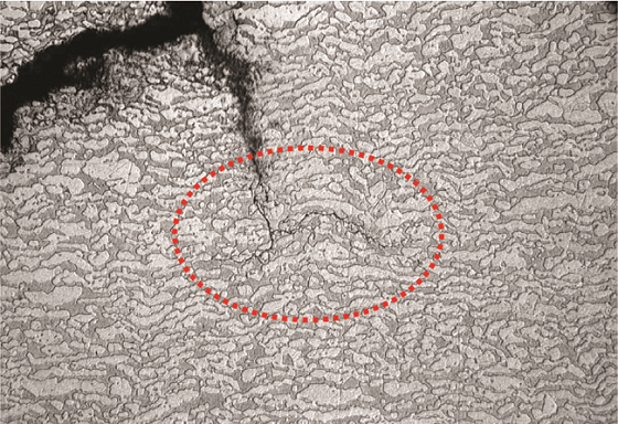
Figures 3 and 4 show transgranular cracks originating at the OD that were observed along with multiple crack initiation sites. The microstructure is typical of DSS. Molten chloride salts were responsible for the localized corrosion. EDS analysis of corrosion products inside the cracks confirmed the presence of chlorides. The base metal was verified to be Type 2205 DSS. SEM fractography indicated cleavage fracture and transgranular SCC.
Case History 3—Outlet Piping for High-Pressure Separator Vapor Coolers at Refinery C
Following the detection of cracking on a girth weld in a 254-mm (10-in) DSS outlet piping for the high-pressure separator vapor cooler in a hydrocracker unit, a 75-mm (3-in) boat sample was removed for failure analysis. The circumferential crack was 140 mm (5.5 in) in length. The operating temperature was 60 °C (140 °F) at 6.9 kPa (2,167 psig), with a reported time of service of 18 to 24 months. Transverse cross sections were removed from the boat sample and mounted for optical microscopy and SEM analysis.
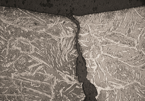
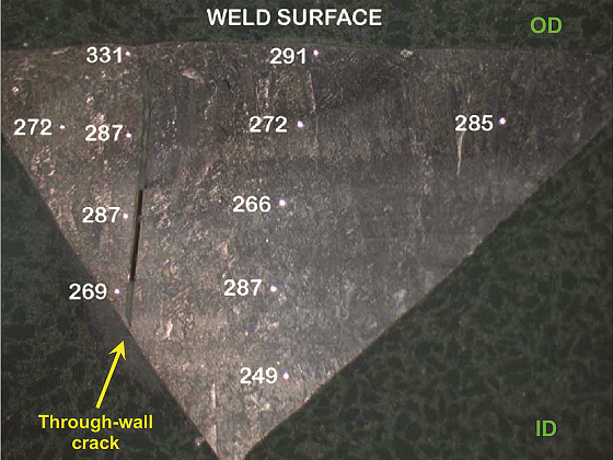
Figure 5 shows an optical micrograph of the cross section. The microstructure was typical of DSS with austenitic laths present at prior ferrite grain boundaries. The crack propagation path was “stepped” and occurred along crystallographic planes. The crack ran perpendicular to the primary stress direction, ran parallel along the weld deposit, and was in the HAZ. SEM fractography demonstrated the transgranular nature of cracking. EDS analysis also confirmed the material to be Type 2205 DSS. Austenite-ferrite counts determined per ASTM E5626 indicated 56% austenite and 44% ferrite, which is acceptable for standard DSS materials. Hardness measurements taken across the cross section (Figure 6) indicated an average value of 281 Vickers hardness (HV). Per NACE MR01037 limits, the average hardness on a DSS weld should not exceed 310 HV, and no individual reading should exceed 320 HV.6-7 In this boat sample, average hardness was within the NACE requirements; however, zones of unacceptable hardness were present in this piping, as evidenced by the high hardness value near the crack (331 HV). Based on the transgranular crack morphology and high hardness readings near the crack, the client concluded that the failure was due to SSC. Similar SSC failures, though rare, have also been reported by other clients for hydroprocessing units. API 938-C1 mentions improper fabrication as the primary cause of SSC failures in DSS, which is also likely what happened in this case.
Conclusions
1.) DSS heat exchanger tubing can undergo Cl-SCC in crude distillation units. In two cases described in this article, intergranular attack was observed in an overhead heat exchanger finned tube, while transgranular SCC was observed in a TPA seamless heat exchanger tube.
2.) Ionic equilibria modeling and process control to avoid concentration of chloride salt deposits can mitigate Cl-SCC.
3.) Periodic visual inspection for surface cracking, as well as penetrant testing and eddy current testing, can be used to detect Cl-SCC.
4.) DSS welds can suffer SSC cracking in hydrocracker units. The third case study described in the article showed evidence of transgranular crack morphology in the girth weld of the outlet piping along with local hard spots. Use of improper welding and fabrication techniques likely caused SSC.
Acknowledgments
The authors thank the Pinnacle Leadership Team for granting permission to publish this work.
† Trade name.
References
1 API 938-C, “Use of Duplex Stainless Steels in the Oil Refining Industry” (Washington, DC: American Petroleum Institute, 2011).
2 J. Sakai, K. Matsumoto, “Experience Survey of Chloride Resistant Alloys in Process Plants,” CORROSION/99, paper no. 385 (Houston, TX: NACE International, 1999).
3 K. Moore, C.A. Shargay, “Duplex Stainless Steel Chloride Stress Corrosion Cracking Risk in the Oil Refining Industry,” CORROSION 2013, paper no. 2520 (Houston, TX: NACE, 2013).
4 D.E. Moore, “Fabrication of 2205 Duplex Stainless Steel REACs in Refinery Hydroprocessing Units,” Materials Technology Institute, 2015.
5 J. Sedriks, Corrosion of Stainless Steels, 2nd ed. (New York, NY: John Wiley & Sons, Inc., 1996).
6 ASTM E562-19, “Standard Test Method for Determining Volume Fraction by Systematic Manual Point Count” (West Conshohocken, PA: ASTM International, 2019).
7 NACE MR0103/ISO 17495, “Petroleum, petrochemical and natural gas industries—Metallic materials resistant to sulfide stress cracking in corrosive petroleum refining environments” (Houston, TX: NACE, 2015).