Internal corrosion of metallic aboveground storage tanks that contain or may contain conductive electrolytes is an issue that cannot be overlooked. A myriad of factors can cause internal corrosion including but not limited to types of materials present, electrolyte chemistry, temperature, presence of coatings, and process flow characteristics.
In particular, the use of dissimilar metals in storage/process tanks can cause internal corrosion issues or negatively impact the effectiveness of a cathodic protection (CP) system, as well as reduce the effectiveness of post-construction corrosion mitigation options.
Standard practices provide criteria that allow corrosion professionals to evaluate the performance of an internal CP system designed for steel structures.1-4 The two most common criteria are:
• A negative polarized tank-to-electrolyte potential of at least -850mV relative to a copper-copper sulphate electrode (CSE)
• A minimum of 100mV of cathodic polarization between the structure surface and a stable reference electrode contacting the electrolyte
In their CORROSION 2019 conference paper,5 authors Natanael Melendez and Stephen B. Gibson of Corrpro Canada, Inc. (Edmonton, Alberta, Canada) analyzed two case studies of corrosion prone tanks that use dissimilar metals and the challenges that arose in providing them with adequate CP.
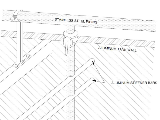
Case I involved an aluminum tank with stainless steel components. In this case study, two tanks operating in a wastewater treatment plant are considered. The tank shell and support structures are an uncoated 5000-series aluminum alloy, while the equipment submerged in the tank is uncoated 304 stainless steel. The dissimilar metals are electrically continuous, the electrolyte is saturated with dissolved oxygen and in continuous motion, and the tops of the tanks are open to the atmosphere.
Figure 1 illustrates localized galvanic corrosion on the aluminum support bars resulting from the coupling of aluminum alloys and stainless steel in a common electrolyte. The authors present multiple options to combat galvanic corrosion in this scenario:
1. Replace the equipment inside the tank with metals similar to the tank shell
2. Replace the equipment inside the tank with an inert metal (such as plastic)
3. Coat the tank internals (internal components and shell)
4. Coat the more noble material (i.e., stainless steel)
5. Apply either of the following CP systems: a sacrificial anode CP (SACP) or an impressed current CP (ICCP)
The authors report that the tank owner chose CP as the most effective method to reduce galvanic corrosion (i.e., option 5). An SACP system was installed (magnesium anodes) because an ICCP system was not deemed to be cost effective. In order to improve current distribution, multiple anodes were installed throughout the tank as per the estimated current requirements. The CP system was evaluated by an interrupted survey. The authors’ opinion is that, during initial tank design phase, a holistic approach that takes corrosion control considerations into account should be utilized.
Case II involved a coated steel tank with an extensive array of bare stainless-steel internal components, which were electrically continuous with the steel tank. Located in an oil and gas facility, the tank is designed to hold a mixture of oil, gas, and water. The tank has a shell that is internally coated, while the stainless-steel internal components are uncoated. Initially, this tank had an SACP system installed to mitigate internal corrosion. However, the sacrificial anodes were consumed prematurely due to the large current required of the uncoated components. The tank had reference electrode ports installed at various locations that were used to monitor the state of the tank’s internal submerged surfaces.

Figure 2 shows the internal components of the tank referred to in this scenario. The authors offer several options for combating galvanic corrosion:
1. Replace the internal tank components with coated steel
2. Coat the stainless-steel components
3. Apply CP
In this case, the decision was made to design a new CP system (i.e., option 3), as it limits the amount of tank downtime. An ICCP system was recommended and installed because of the high current requirement of the stainless steel. The ICCP anodes were installed in existing flanges. However, only some of the existing flanges were utilized due to accessibility issues.
While it is possible to install a new ICCP system using the existing flanges, the authors advocate for a collaboration between the tank designer and corrosion professionals to ensure that proper corrosion mitigation techniques are applied during the design stage. As with Case I, they argue in favor of a holistic approach to corrosion control that takes corrosion control considerations into account during the initial design phase.
For both Case I and Case II, the authors make the following recommendations to tank designers and corrosion professionals:
• Identify any dissimilar metal locations within the tank
• Determine how the galvanic coupling will affect the corrosion control system
• Discuss additional options on how to mitigate galvanic corrosion
References
1 NACE Standard Practice SP0196-2015, “Galvanic Anode Cathodic Protection of Internal Submerged Surfaces of Steel Water Storage Tanks” (Houston, TX: NACE International).
2 NACE Standard Practice SP0388-2014, “Impressed Current Cathodic Protection of Internal Submerged Surfaces of Carbon Steel Water Storage Tanks” (Houston, TX: NACE International).
3 NACE Standard Practice SP0575-2007, “Internal Cathodic Protection (CP) Systems in Oil-Treating Vessels” (Houston, TX: NACE International).
4 American Petroleum Institute (API) Recommended Practice 651, “Cathodic Protection of Aboveground Petroleum Storage Tanks” (Washington, DC: American Petroleum Institute).
5 N. Melendez, et al., “Challenges in Providing Effective Internal Corrosion Protection for Aboveground Storage Tanks,” CORROSION 2019, paper no. 13194 (Houston, TX: NACE International, 2019).