When exposed to harsh operating environments, reinforced concrete cooling towers can develop severe corrosion of embedded steel reinforcement that leads to concrete delamination and spalling. Because of their size, geometry, and operational constraints, determining the condition of cooling towers can be challenging; however, careful assessment provides critical knowledge for effectively ascertaining their structural health so maintenance and repairs can be planned to maximize service life.
At an electric power plant in the Mid-Atlantic region of the United States, two identically designed reinforced concrete hyperbolic shell natural draft cooling towers serve two generating units (Unit #3 and Unit #4) that run intermittently to meet peak energy grid demands. Each tower is the main component of a closed-cycle water cooling system that draws brackish process water from the nearby river.
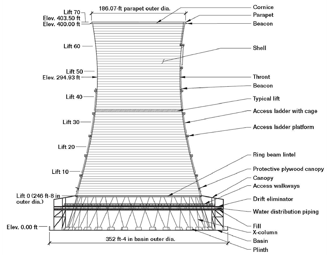
The older of the two towers, which serves Unit #3, was constructed in 1974 and placed into service in 1975. The second tower, serving Unit #4, was constructed in 1975 and placed into service in 1981. Both cooling towers are ~400-ft (122-m) tall with horizontal cast-in-place construction joints located at every ~5-ft (1.5-m) height increment to form 70 identifiable “lifts.” Each tower’s shell is about 8-in (203-mm) thick along its height, with the thickness incrementally increasing in the five lifts at the bottom to form a 36-in (914-mm) thick ring beam and in the three lifts at the top to form a 26-in (660-mm) thick cornice.
The interior and exterior faces of the concrete shells are each reinforced with a mat of steel reinforcing bars running vertically and circumferentially. From the tower’s throat upwards, the reinforcing bars are typically #5 bars (~16 mm in diameter) spaced at 12 to 16 in (305 to 406 mm) on center in each direction. The volume of reinforcing steel increases toward the tower’s base, where #7 bars (~22 mm in diameter) are spaced vertically at 5 in (127 mm) on center and #8 bars (~25 mm in diameter) are spaced circumferentially at 6 in (152 mm). The nominal concrete cover over the reinforcement is 2-in (51mm) thick. The shell is supported by 32 precast reinforced concrete X-columns that are ~60-ft (18-m) tall with a 20- by 33-in (508- by 838-mm) cross section containing 16 vertical #11 bars (~36 mm in diameter).
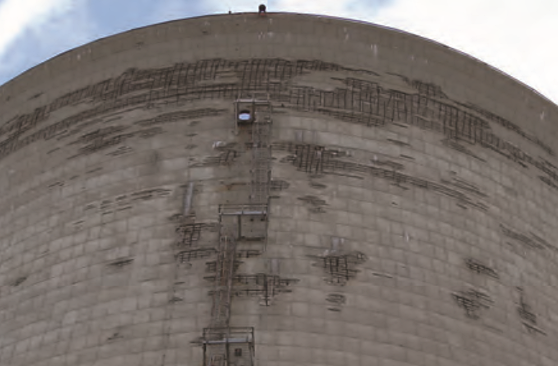
In the mid-1980s, concrete deterioration was initially observed on the exterior face of the Unit #3 cooling tower shell. Over time, concrete deterioration progressed in the cooling towers for both Unit #3 and Unit #4. This included large areas of concrete delamination and spalling at the shell exteriors, areas of concrete delamination at the shell interiors, and cracking and corrosion staining in the supporting X-columns. To limit the risk of deteriorated concrete falling from the shells, the owner employed a contractor on several occasions to remove loose delaminated concrete from the towers.

Multiple condition assessments were performed in 2006 to characterize deterioration mechanisms and determine the structural integrity of the two towers, as well as develop repair plans to meet the owner’s service life requirement of 25 years.
The towers’ assessments included visual inspections performed from grade, catwalks, tower ladders, the cornice, and the basin. Hands-on inspections also were performed from swing stages and aerial lifts. During these inspections, nondestructive testing (NDT) was performed, such as hammer sounding, cover readings, and half-cell potential readings. Inspection windows were made at areas of interest in the concrete, and core samples were extracted for petrographic analysis and chloride content testing.
The results of the evaluation and subsequent repair strategy for the Unit #3 tower are presented in a CORROSION 2018 paper by Matthew B. Gries, Kevin A. Michols, and John S. Lawler with Wiss, Janney, Elstner Associates, Inc. (Northbrook, Illinois, USA); David W. Whitmore with Vector Corrosion Technologies, Ltd. (Winnipeg, Manitoba, Canada); and Matt Miltenberger with Vector Corrosion Services, Inc. (Tampa, Florida, USA).
According to the authors, the 2006 assessment found large areas of spalled concrete throughout the exterior surface of Unit #3’s shell, with a greater concentration on the upper third of the tower. Delaminations identified on the interior face of the shell by NDT also were predominantly located in the upper third of the shell, which indicated that corrosion was occurring on the interior face of the shell. Results of half-cell tests performed at the interior face of the shell above the tower’s throat (lifts 48 through 68) ranged from 0.02 to –0.61 V vs. a copper/copper sulfate (Cu/CuSO4) electrode (CSE), which also suggested some active corrosion in the upper part of the tower.
Concrete samples from the tower were laboratory tested, and results showed significant chloride penetration to the depth of the reinforcing steel. Chloride levels were typically higher in the upper portion of the tower—up to 11 times more than the corrosion threshold concentration at both the interior and exterior surfaces of the shell, and up to three and six times higher than the threshold concentration at the depth of exterior and interior reinforcement, respectively.
Additionally, visible deterioration was found in 30 of the 32 X-columns. The lower half of the X-columns (below the fill) exhibited a greater amount of deterioration, which primarily consisted of longitudinal cracking at the corners that was associated with delaminations of the cover concrete from corrosion of embedded steel reinforcement.
By 2010, the amount of spalled concrete on the shell’s exterior had increased, but the most dramatic change was a substantial increase in the extent of delaminations at the interior face of the shell, which signified an increase in the rate that corrosion-related damage was occurring. This high growth rate of concrete delamination was considered a significant risk to the structure’s integrity because the structural stability and strength of the tower shell rely on the concrete wall thickness being intact so the reinforcing steel is capable of resisting inplane tensile stresses as well as out-of-place bending stresses.
Because the delaminations in the upper section of the tower shell had resulted in widespread interior and exterior deterioration of the concrete, the owner decided to perform an engineered demolition and rebuild of the upper one-third of the tower shell. Below the throat, concrete deterioration was less severe and structural concrete repairs were selected, which included localized partial-depth concrete repairs at both the interior and exterior of the shell with some full-wall thickness repairs. Since the X-columns had sufficient capacity in their observed state, they were not repaired.
Corrosion mitigation of the reinforcing steel was specified for the entire shell and supporting X-columns to protect against future deterioration and maintain the tower’s structural integrity. A hybrid cathodic protection (CP) system, comprised of both galvanic CP and impressed current CP (ICCP), was installed on this tower. For the shell, ICCP was selected because the voltage levels at different locations on the large shell could be controlled over the course of the CP system’s service life. Since the X-columns are exposed to a wet environment and a wide range of service temperatures (from –20 to 50 °C), galvanic CP was chosen to protect them because its components have the ability to withstand the harsh environment.

The ICCP system is comprised of 48 individual zones, which are evenly distributed around the tower shell in six vertical stacks of eight zones. Each zone has four embedded reference electrodes, which is a total of 192 reference electrodes for the entire shell, to monitor the polarization of the steel reinforcement. The lower three zones—the heavily reinforced, thickened concrete base of the shell—have discrete titanium suboxide ceramic tube anodes. The next three zones use mixed metal oxide (MMO) ribbon mesh anodes grouted into slots cut into the exterior surface to protect the repaired height of the existing shell, and the top two zones use MMO ribbon mesh anodes placed between the reinforcing layers in the reconstructed portion of the shell above the throat. In total, over 6 mi (9.7 km) of ribbon mesh anodes and over 4,300 discrete ceramic tubular anodes were installed on the project.
At each vertical stack, a rectifier cabinet that contains eight independent transformer/rectifier direct current (DC) power supplies—one for each zone—and a remote monitoring unit (RMU) that monitors and logs the reference electrode data along with the DC voltage and current of each individual circuit is located on the canopy walkway. The RMU can be controlled by web-based software to measure voltage, current, and potentials, as well as perform polarization decay testing.
The galvanic CP system on the X-columns uses galvanic jackets that contain alkali-activated zinc anodes installed with cement mortar inside stayin-place fiber-reinforced polymer forms. These galvanic anodes essentially operate as a low-voltage battery that supplies protective current to the columns’ reinforcing steel. These jackets do not require any maintenance or monitoring to provide long-term corrosion protection; however, four of the 32 X-columns were instrumented with manganese dioxide (MnO2) reference electrodes wired for monitoring so representative data can be obtained to assess the performance of the galvanic CP system. For these columns, monitoring boxes were mounted at the base of the tower shell so they would be easily accessible from the canopy walkway.
The system was energized in March 2017. Adjustments were made after two weeks, three months, and six months. Further testing, adjustments, and inspections will occur every six months. More information on the CP systems can be found in CORROSION 2018 paper no. 11005, “Evaluation and Repair of Natural Draft Cooling Towers,” by M.B. Gries, et al.