Editor’s note: Learn more about corrosion of chromium steel in this Materials Performance quarterly special feature, “The Science Behind It.” After you’ve read the MP article on the failure analysis of a S13Cr-110 premium joint tubing string fracture in a high-pressure, high-temperature well, explore the science behind the corrosion problem, which is presented in several related CORROSION articles listed at the end of this story.
Tubing made of S13Cr-110 (UNS S41426) stainless steel is sensitive to the environment, and stress corrosion cracking (SCC) easily occurs. Cause analysis for the failure of S13Cr-110 single tubing has been studied by many authors;1-4 however, there are few papers addressing fracture-cause analysis of multiple S13Cr-110 tubes in one highpressure, high-temperature (HPHT) well that consider well depth, stress condition, environment caused by the medium, and failure position of the tubing.
Two lengths of 89-mm diameter and 6.5mm thick, S13Cr-110 tubing with premium joints fractured, and nine lengths of 89-mm diameter S13Cr-110 tubing cracked in one HPHT well after acidification and spray as part of production. Here, premium joints refer to box and tube joints that exceed API Spec 5B.c This article discusses the tests and analysis that were carried out to determine the cause of the multiple tubing failures.
Test Results and Analysis
Tubing Fracture Position and Nondestructive Testing Results
Segment No. 418 of the 89-mm diameter tubing with premium joints broke at the pin vanish point—where the tube’s pin threads are no longer visible on the tube connection made up in the mill. The well depth of that fracture location was 4,146 m. Segment No. 432 of the 89-mm diameter tubing, with premium joints and coupling made by the mill, also fractured at the pin vanish point (Figure 1) of the connection made up in the mill, but at a well depth of 4,285 m. The total depth of the well is 6,815 m and the packer position depth is 6,714 m.
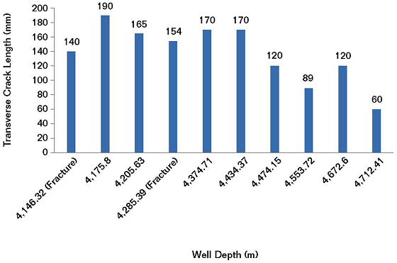
Nondestructive testing (NDT) identified transverse cracks on eight lengths of tubing at the pin thread vanish point of the connection made up in the mill. The location of the cracks and the fracture positions of the tubing were coincident. NDT also showed there was a longitudinal crack on one length of the pipe tube body at a position near the connection made up in the field. The circumferential length of fractures and cracks on 10 pin vanish point specimens and their depths in the well are shown in Figure 2.
Figure 2 shows that fractures and cracks of tubing were at well depths of 4,146 to 4,712 m, with a total range of 566 m. Ten lengths of tubing failed at the pin vanish point of the connection made up in the mill, which accounted for 91% of the total failures.
Results of Fractography and Metallography
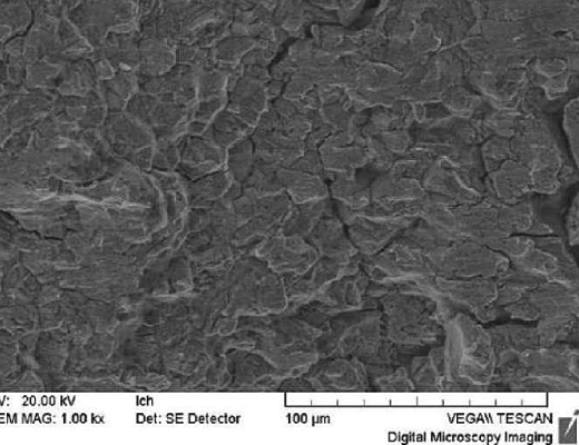
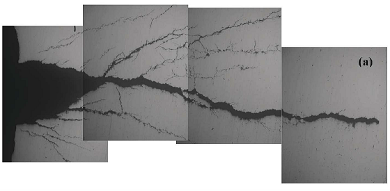
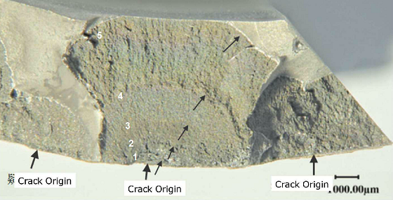
Fractures and cracks of the S13Cr-110 tubing with premium joints were the result of SCC that developed under conditions that included tensile stress in a corrosive medium (Figures 3 and 4). Fatigue failure also took place due to alternating loads borne on the tubing string (Figure 5), and many corrosion pits produced in the early stage that accelerated SCC and fatigue cracking.
The tubing material performance was in accordance with ISO 13680 and the owner’s requirements, but it did not perform well when exposed to the HPHT and aggressive environment where corrosive chloride, sulfide, and carbon dioxide (CO2) were present.
Discussion
Analysis of the Failure Position in the Well
The tensile load borne by the tubing string was greater near the wellhead than the bottom of the well because of the tubing weight.6 The tubing fractures and cracks were located at depths of 4,146 to 4,712 m, and not where the maximum tension load on the tubing string was present.
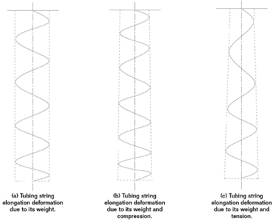
The load borne by the tubing string in the well included tensile stress from its weight and contraction with cold, as well as compressive load caused by heat expansion and internal, external, and vibrational loads. The stress condition of the tubing string under these loads is illustrated by Figure 6. Tubing string elongation deformation due to its weight is shown in Figure 6(a), tubing string elongation deformation due to its weight and compression is shown in Figure 6(b), and tubing string elongation deformation due to its weight and tension is shown in Figure 6(c).
The tubing string expanded from heat during gas production. Because the tubing string was fixed to the wellhead by the oil production tree and held in place by the packer near the bottom of the well, it experienced bending as shown in Figure 6(b). In this case, the more the tubing string was bent, the more likely the tubing would crack.
Alternatively, the tubing string contracted from cold during the acidifying process. The stress condition of tubing string at the beginning of acidification is shown in Figure 6(c). When the tubing string temperature was reduced, it gradually shortened and became straighter. Additionally, the tubing string was subjected to internal pressure and vibration load from the natural gas flow rate change and pump pressure fluctuation during acidification injection and discharge. The tubing failed from SCC, however, corrosion fatigue failure characteristics were also found on the fracture surfaces, which indicated alternating loads were borne by the tubing string during these processes.
Although the penetration cracks on the tubing string were not created during production, the tubing might have been damaged, or its plasticity and toughness reduced, during intervals of significant bending. Once cracking occurred from the action of alternating loads and the corrosive medium, the tubing string would have experienced a leak or break.
The tubing string present in the well was mainly composed of six types of tubing. Among them, the 89-mm diameter tubing was the smallest in diameter and comprised the least amount of section area.
Stiffness is determined by the elastic modulus multiplied by the area of the section. If the elastic modulus of the tubing material is constant, then the tubing stiffness is proportional to its section area. Therefore, the smaller the section area, the easier it is to bend the tube.
As mentioned previously, the fractures or cracking of the tubing occurred at well depths of 4,146 to 4,712 m, which is a length of 566 m with the midpoint of this length at a well depth of 4,429 m. The entire 89-mm diameter tubing string was located at well depths between 2,892 m and 6,293 m, which is a length of 3,401 m with the midpoint of this length at a well depth of 4,593 m. The tubing fractures and cracking were located at or near the middle of the 89-mm diameter tubing string. This indicates that the fractures and cracking were the result of the bending load instead of the tensile load. The 89-mm diameter tubing had the smallest section area among the entire tubing string and could have easily bent to failure under the loads due to fluctuations in temperature that caused tubing expansion and contraction.
Analysis of the Fracture and Crack Position on the Tubing
The tubing’s pin and box connections formed a double layer of material at the joints,7 so the wall thickness of a premium connection—and its stiffness—was greater than that of the pipe body. The thickness change at the end of the coupling was an area of stress concentration on the pipe body. The ratio of the joint section to the pipe body was only 36.2%.
Since the transition point of the tubing section was at the pin’s vanish point, deformation took place at the pin’s vanish point first when the tubing string was subjected to a bending load. It was further shown that the tubing easily failed at the end of the joint under bending load in accordance with the observed transverse fracture or crack position at the pin’s vanish point. Additionally, there was a stress concentration at the pin’s vanish point according to the results of finite element analysis for the connection.
Analysis of the Fracture at the Mill’s Pin Vanish Point
Since there was little load difference for the mill-prepared connection and fieldprepared connection for one joint, the reason why 10 lengths of tubing fractured or cracked at the pin vanish point for the connection produced at the mill is related to the difference between torque used to make up connections at the mill and in the field. It is known that the minimum torque used to create a coupling at the mill was 8.2% higher than what was used to make a coupling in the field. The optimum torque to create a coupling at the mill is 3.7% higher than that for a coupling made in the field. The stress at the pin thread vanish point for the premium connections was, therefore, a high-stress location.
The total stress borne on the tubing joint is a combination of installation stresses and stresses applied during operation. So, the greater the connection’s makeup torque, the more severe the as-installed interference of the box and pin, which leads to more residual stress after assembly, and then more tensile stress borne by the tubing joint. It was shown that tubing transverse fractures or cracks at the pin’s vanish point for connections produced at the mill were related to its use of higher torque.
Temperature Effect on Tubing Failure
For this well, the temperature ranged from 41.75 to 43.59 °C at the wellhead. The temperature was 171 °C at a depth of 6,794 m, where gas is stored. In accordance with the temperature gradient determined by Equation (1):
(171 – 43.59)/6,793.5 = 0.018755 (1)
The temperature ranged from 104.5 to 132.1 °C at depths from 4,146 to 4,712 m where the tubing fractured and cracked. The temperature was 127 °C at a depth of 4,429 m, which is the midpoint of the failure depth range. It should be noted that S13Cr-110 is most sensitive to SCC at temperatures from ~105 to 132 °C.
Conclusions
• The tubing failure mechanism was SCC and corrosion fatigue.
• The temperature was 105 to 132 °C at depths of 4,146 to 4,712 m where the tubing broke and cracked. S13Cr-110 is most sensitive to SCC at temperatures between 105 and 132 °C.
• The failure load borne by the tubing string mainly resulted from bending due to expansion with heat and contraction with cold.
• Ten lengths of tubing transverse fractured or cracked at the pin’s vanish point of connections made by the mill, which was related to higher make-up torque being used at the mill than in the field.
References
1 Y. Ding, et al., “Cause Analysis on Washing out of ⌀88.9mm×6.45mm S13Cr-110 Tubing,” J. Physical Testing and Chemical Analysis Part A: Physical Testing 10 (2011): pp. 663-667.
2 S.L. Lv, et al., “Analysis on Causes of a Well Casing Coupling Crack,” MP 51, 4 (2012): pp. 58-62.
3 S.L. Lv, et al., “Cause Analysis on Tubing Corrosion in Well YH 301,” J., Corrosion & Protect. 29, 11 (2008): pp. 706-709.
4 S.L. Lv, et al., “Analysis of Premium Connection Downhole Tubing Corrosion,” MP 47, 5 (2008): pp. 66-69.
5 API SPEC 5B, “Threading, Gauging, and Inspection of Casing, Tubing, and Line Pipe Threads” (Washington, DC: API, 2017).
6 P.B. Yuan, S.W. Guo, and S.L. Lv, “Failure Analysis of High-Alloy Oil Well Tubing Coupling,” MP 49, 8 (2010): pp. 68-71.
7 S.L. Lv, et al., “Analysis of N80 BTC Downhole Tubing Corrosion,” MP 43, 10 (2004): pp. 35-38.