One of the most common drivers of concrete repairs is corrosion of the concrete’s steel reinforcement. This type of corrosion is often caused by chloride ions in the environment entering the concrete and eventually reaching the embedded steel. When the build-up of chloride ions at the steel reaches a certain concentration, and moisture and oxygen are present at the concrete/steel interface, the steel’s passive oxide layer will break down and corrosion can initiate.
There are many ways to repair concrete degradation and mitigate corrosion of the underlying steel; however, until recently there wasn’t a standard method to evaluate the effectiveness of the numerous corrosion-control technologies incorporated into concrete repairs. This need prompted a research program, funded by the Strategic Development Council (SDC) of the American Concrete Institute (ACI) (Farmington Hills, Michigan) and carried out by the U.S. Bureau of Reclamation (Washington, DC), to develop a test protocol, M-82,1 for evaluating concrete repairs—specifically topical surface treatments, surface membranes, and patch repairs with and without sacrificial anodes. By comparing sample concrete specimens treated with different corrosion mitigation technologies to control concrete specimens receiving no corrosion treatment, the protocol provides a reliable way to predict corrosion mitigation by a surface-applied or integral repair treatment.
According to NACE International member Neal S. Berke, FNACE, with Tourney Consulting Group (Kalamazoo, Michigan), what has concerned practitioners in the past is that corrosion starts appearing around a new concrete patch once a repair has been made. Before the repair, he explains, the original corroding steel acts as a sacrificial anode and keeps the reinforcing steel around it from corroding. When the patch repair replaces the corroding steel with new steel, he says, the new steel in the repair location often becomes a cathode, which causes the steel adjacent to the patch repair to act as a sacrificial anode and start corroding.
One way to mitigate corrosion of the reinforcing steel around a patch repair, which is known as ring corrosion or a halo effect, is to embed sacrificial anodes into the patch repair to provide corrosion protection to the old steel adjacent to the new steel in the patch. This type of repair removes an area of distressed or damaged concrete, replaces the corroded reinforcing steel if necessary and attaches a sacrificial anode to the steel, and then fills the hole with a cementitious repair material, most often concrete. Patch repairs with sacrificial anodes are most common on bridge decks and parking decks, Berke comments, but can also be used in applications such as concrete walls and beams. The challenge is to determine which anode will work best in the field. How much steel the anode is able to protect depends on how much current it’s able to produce, which is contingent on the anode’s size and material of composition, he says.
The M-82 test protocol, which took about three and a half years to develop, provides a standard method to test and evaluate how well a particular anode mitigates corrosion in the areas adjacent to the concrete patch. This aspect of the test protocol is discussed in CORROSION 2016 paper no. 7524, “Test Protocol to Evaluate the Effectiveness of Embedded Sacrificial Anodes in Reinforced Concrete.”2

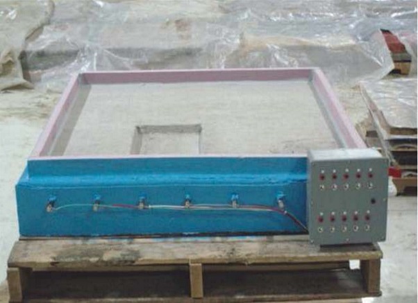
To represent conditions in the field, the test protocol calls for relatively large steel-reinforced concrete samples—40 by 40 by 5.5 in (1,016 by 1,016 by 140 mm)—that are big enough to determine the range of protection provided by the anode, but small enough to be moved by a forklift truck and stored on shelves. Five concrete sample slabs are used as control specimens, and five are used as test specimens that incorporate the various anodes being tested.

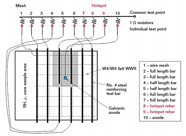
Eight reinforcing steel bars are located near the top of each sample slab and welded-wire reinforcement (WWR) is placed near the bottom of each slab to act as the cathode. A portion of the sample slab does not contain rebar so concrete core samples can be taken during the test to determine chloride content. A 1-in (25-mm) concrete cover is placed over the rebar. To speed-up corrosion and mimic conditions that call for a patch repair in the field, the slabs have a section on the surface called a “hotspot,” where the concrete cover is reduced to 0.75 in (19 mm). The two steel bars underneath the hotspot are half-length to facilitate easy removal for a patch repair. The concrete specimens are moist cured for seven days and air dried for 21 days.
When chloride-induced corrosion of rebar is present in concrete, macrocell corrosion with a large cathode and local anode often occurs and causes local corrosion attacks and cross-section reduction of the steel rebar.3 To create a macrocell in the sample slabs, the individual steel reinforcing bars and WWR are connected to a junction box attached to the side of the slab through a 1-Ω resistor. By measuring the voltage drop across the resistor, the macrocell corrosion current between each bar and the WWR can be determined. The two half-length bars in the hotspot are connected individually so the corrosion current both inside and outside of the patch area can be verified.
To initiate rebar corrosion, a 5% sodium chloride (NaCl) solution (~5 gal [19 L] per specimen) is poured over the slab at a depth of between 0.75 to 1.5 in (38 mm) and allowed to pond. After 14 days of ponding, the solution is drained and the specimen dries for an additional 14 days. A complete cycle is 28 days. Macrocell currents are measured at the end of the chloride ponding period before the solution is drained. After every three 28-day cycles, once the NaCl solution is removed, a corrosion potential contour map of the slab is created. Corrosion is considered to have initiated the first time a steel reinforcing bar has a potential reading more negative than –300 mV vs. a copper/copper sulfate (Cu/CuSO4) reference electrode (CSE) and the macrocell current is >0.03 mA, or when the macrocell current is >0.03 mA for two cycles.
At corrosion initiation, a core sample is taken from the slab for chloride analysis, another corrosion potential contour map is created, and then patch repairs are made to the hotspot. The samples with sacrificial galvanic anodes are repaired the same way as the control samples, except that an anode is attached to the bar and wired to the junction box.
“By running a separate wire from the anode to the junction box, we can actually measure its current, so we are able to see how much current the anode sends to the bars around it,” Berke explains. Ideally, the anode sends enough current to the surrounding bars so that they become cathodes, he adds. After the repairs are made, the ponding cycles and macrocell corrosion cell testing continue, as well as complete potential contour mapping. When 80% (four out of the five) of the control slabs have corrosion-induced concrete cracking over the reinforcing bars, the test period continues for two more 28-day cycles; and then the test is concluded. In its entirety, the test protocol can last anywhere from one and a half to two years.
During the test, key parameter values that should be noted for later evaluation of the test results include time to corrosion initiation and chloride content at corrosion initiation; and time to repair, integrated current at repair, chloride at repair, and potential map at repair.
Upon test completion, another concrete core sample is taken for chloride analysis, a final corrosion potential contour map is produced, and the lengths and widths of the concrete cracks are measured for all the specimens. Key parameter values to note at this point are combined macrocell currents after repair to the end of testing, chloride contents at the end of testing, and crack dimensions at the end of testing. The top layer of concrete above the steel reinforcing bars is then removed from the specimens so the steel bar is visible (both front and back) and can be photographed in 6-in (152-mm) increments. Using tables in M-82 as a guideline, the surface corrosion of the steel in each slab is classified by percentage of surface area corroded and degree of corrosion damage.
According to the conference paper, the sacrificial anodes are considered effective if the difference in the combined macrocell currents after repair is less than that in the control slabs, and cracking in the slabs with the anodes is reduced. Since considerable corrosion could occur before the repair treatment, there could be corrosion on the reinforcing bars in both the control and sacrificial anode slabs.
Providing a consistent test set-up so that different sacrificial anodes in concrete can be compared under the same test conditions is important for several reasons, Berke says. It provides a standard method with a rigorous, unbiased test protocol that everyone can use to test planned concrete repairs with sacrificial anodes. It also provides a method to test and compare anode materials to determine if one material outperforms another. Additionally, the test protocol can be used to develop new sacrificial anode materials for concrete repairs.
Contact Neal S. Berke, Tourney Consulting Group—e-mail: NBerke@TourneyConsulting.com.
References
1 M-82, “Standard Protocol to Evaluate the Performance of Corrosion Mitigation Technologies in Concrete Repairs” (Washington, DC: U.S. Bureau of Reclamation, 2014).
2 N.S. Berke, D. Little, B.E. Bucher, K.F. Von Fay, “Test Protocol to Evaluate the Effectiveness of Embedded Sacrificial Anodes in Reinforced Concrete,” CORROSION 2016 paper no. 7524 (Houston, TX: NACE International, 2016).
3 B. Elsener, “Macrocell Corrosion of Steel in Concrete—Implications for Corrosion Monitoring,” Cement and Concrete Composites 24, 1 (2002): pp. 65-72.