Advanced robotic inline inspection (ILI) crawlers have now been successfully used to inspect two previously unaccessible North American pipelines on the Trans-Alaska Pipeline System (TAPS) and the Transco Pipeline.
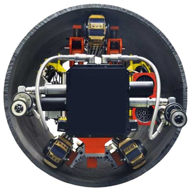 Developed by Diakont (San Diego, California), these robotic crawlers (Figure 1) use rugged track systems to traverse difficult pipe geometries and inspect lines that are often inaccessible to traditional flow-driven, smart pig tools. The crawlers feature a tank-tread design that expands firmly into the internal diameter (ID) of the pipe for traction.
The crawler uses dual base tracks for navigation on horizontal surfaces and a single top track to stabilize it. The top track extends to the top of the pipe to provide the necessary traction to hold the crawler rigidly in place while inspecting difficult pipe geometries such as vertical sections.
Meanwhile, a 1,500-ft (457-m) long umbilical cable connects the crawler to a central control station and provides for power, real-time data collection, and control of the crawler’s tracks and sensor suite. A steel retrieval cable is also connected to the back of the tool for extraction in the event of a power failure.
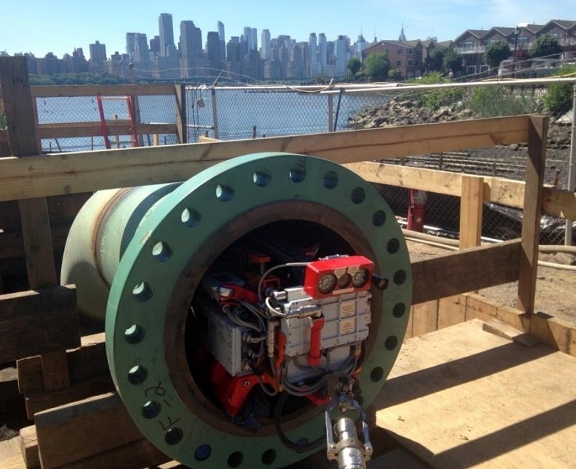
The crawler can be inserted into any access opening (e.g., a removed valve or flange, or a cut spool) that is at least 22-in (0.5-m) wide, as shown in Figure 2.
The robotic crawler used to inspect these two previously unaccessible lines included electromagnetic acoustic transducer (EMAT) ultrasonic testing sensors to measure pipeline wall thickness and locate corrosion damage, while a laser profilometry gauge was used to make a detailed map of the pipeline’s inner surface. That map detailed surface pitting and other irregularities while also taking fine measurements of individual ID anomalies that could contribute to wall loss.
The crawler was also equipped with a video camera to create a video record of each pipeline’s interior.
Unlike conventional ultrasonic testing (UT) instruments that require liquid couplant between the transducers and pipe body to transmit ultrasonic signals, the EMAT instrument on the crawler does not require any couplant. This makes it ideal for gas pipeline inspections where adding liquid within lines is not advisable.
All sensor data feed back to the inspection technicians in real time via the umbilical cable, thus giving same-day assessment results to pipeline operators, says Aaron Huber, marketing supervisor at Diakont. Huber explained the technology and related case studies in a presentation1 at the NACE International Corrosion Risk Management Conference, held from May 23-25 in Houston, Texas.
Transco Inspection
The construction of new apartment buildings and condominiums in urban areas can create high-consequence areas (HCA) for existing pipelines. This was the situation that the pipeline operator faced when new apartment buildings were built on the edge of the Hudson River near the Transco Pipeline system in northern New Jersey (Figure 3).
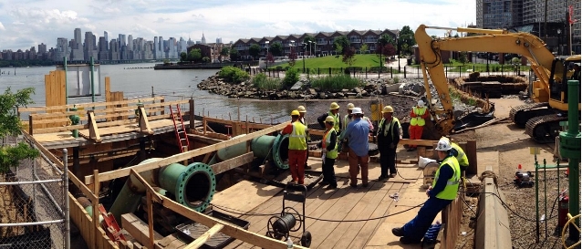
In this case, some of the unpiggable pipelines within those HCAs had never been inspected using ILI tools, and the U.S. Pipeline and Hazardous Materials Safety Administration (PHMSA) now requires specific integrity management programs for many of those lines.
The HCA piping on the Transco line consists of two 24-in (0.61-m) lines running parallel to each other underneath the Hudson River. Since the lines had no external access, and the pipe access was only available on one side of the Hudson River, inspecting those lines proved to be quite challenging, so the integrity engineers turned to ILI solutions.
The inspection tool would have to enter and exit the pipe from the same location—thus ruling out traditional smart pigs, which require retrieval from the end of the line following inspections.
After a live demonstration of the robotic crawler’s capabilities in similar pipe mockup, the pipeline operator chose the crawler for its urban pipeline inspection.
The operator prepared for inspection by removing tees in the valve yard near the edge of the Hudson River to create access points for each buried pipeline. The operator also installed temporary vertical leg sections on the pipelines to bring the access points above the water level. In addition to making the pipeline entry point more accessible, installing the pipe extensions also decreased the risk of getting water in the line during inspection.
After installing those extensions, the operator blew the lines dry to remove the remaining product and excess condensation.
Two inspection teams then mobilized two robotic crawler tools to inspect the twin gas lines simultaneously and minimize the downtime of the pipeline.
Both of the robotic crawlers were hand-loaded into the pipes. While traveling through the entire inspection length, the robots took video of the interior and surveyed pipe elements. Technicians then reversed the crawlers back to the launch point and exchanged the high-definition video modules for EMAT sensors to inspect the pipe in auto-scan mode.
After completing the automatic scan, inspection technicians manually drove the robotic crawlers back to every location with an indication of a potential defect for detailed characterization. Throughout the inspection, data analysts reviewed the data in real time, monitored tool operations via telemetry, and recorded precise pipeline geometric data, which were incorporated into a pipe tally in the pipe feature list report.
The pipeline inspections went smoothly, project officials say, and the lines were completed ahead of schedule. The operator took advantage of the extra availability of the inspection crews and actually arranged the inspection of an additional 800 ft (244 m) of pipeline beyond the original project scope.
The integrity assessment of the Transco pipeline sections showed the pipe to be in excellent condition, with the only abnormalities uncovered during the inspections being a few small pieces of wax on the lower region of the pipe (Figure 4).

With the integrity validated, the operator opted to quickly put the pipeline back in service while also making plans to install permanent tees to the pipelines to facilitate future inspections without requiring any excavation or temporary leg installations.
“According to the pipeline integrity manager, the robotic tool helps solve a problem that has been plaguing the pipeline industry for years,” says Jonathan Minder, an ILI sales engineer at Diakont.
TAPS Pump Station Inspection
In the case of the TAPS, the inspection area was part of the system’s Pump Station 03 (PS03) facility. The inspection of PS03 was performed in the aftermath of a crude oil leak to containment that occurred from a section of underground line at Pump Station 01 (PS01) in 2011.
In addition to being underground, the inspection area was encased in a sand-cement slurry and had difficult geometry for traditional ILI tools to navigate, including vertical sections, a horizontal tee, and multiple back-to-back bends with elevation changes. But these geometries were easily navigated by the advanced robotic inspection crawler.
After 2011, remotely operated ILI tools for inspecting unpiggable facility piping became much more available. Since reconstructing the piping above the ground could cause a safety problem in the event of a pressure surge, the operator chose to conduct an inline inspection. The operator reviewed the modern ILI technologies and selected a bi-directional robotic ILI crawler to inspect the pipeline at PS03.
During the planning phase for the PS03 inspection, two key concerns were identified. One was the crawler’s ability to negotiate the pipeline geometries, and the second was the time investment required for a successful inspection.
Before approving the tool to perform the PS03 inspection, the operator tested the crawler on pipelines at Pump Station 10 (PS10), which had been removed from service several years earlier. PS10 was selected because it had piping that was similar to other operating stations, including PS03, and could thus be used to validate the tool’s inspection capabilities.
The crawler successfully negotiated the PS10 inspection area, including vertical sections, 90-degree bends, transitions from 36-in (0.91-m) to 48-in (1.22-m) pipe, and manifolds with multiple offtakes. The crew also showed the ability to manually extract the tool by simulating a power failure, using the steel retrieval cable to pull the crawler out of the pipeline. That function was essential to the operator, since it proved there was no risk of the crawler becoming stuck in the line.
The PS10 testing also confirmed that cleanliness of the pipe was critical for the EMAT UT sensors to collect accurate data on pipe wall conditions. Pipes that were cleaned to abandonment specifications were successfully examined, but another section of pipe could not be inspected due to heavy scale from exposure to the atmosphere. While this type of scale was unlikely in the PS03 lines filled with crude, it was determined that excessive scale of any type could cause issues, including ultrasonic signal loss and the obstruction of visual anomaly analysis.
As a result, a work crew thoroughly cleaned the inspection area to remove accumulated wax and other debris prior to the PS03 inspection. After flushing hot oil from the main line through the relief piping, the cleaning crew packed the line with 16,000 gal (60,567 L) of diesel fuel to act as a solvent. Then, the diesel flush was followed by a high-pressure wash with about 100,000 gal (378,541 L) of hot water. After that cleaning process, the inside of the pipe appeared like new, with some original stenciled lettering becoming visible.
From there, an inspection plan comprised of five routes was created to access the complex PS03 piping systems. The pipelines inspected included the suction relief line, the storage tank line, the discharge relief line, and the booster pump suction riser. All of the pipelines inspected had a 36-in (0.91-m) outside diameter (OD), except for the 20-in (0.51-m) suction riser. Meanwhile, the discharge relief line was split into two routes to accommodate its especially difficult geometry.
On each inspection route (Figure 5), the crawler performed a visual inspection to record pipeline geometry and document any gross anomalies found on the ID. The crawler then conducted an automatic EMAT scan of the straight pipeline sections and manual scans in the elbows and fittings to detect anomalies such as general corrosion, pitting, and cracking.
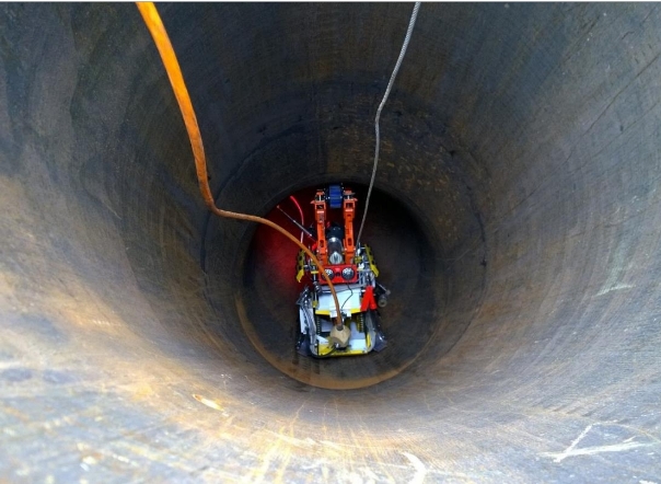
After the EMAT scan, the robot operators navigated the tool back down the pipeline and stopped at the location of each anomaly to perform a detailed manual inspection. These included all anomalies detected during the visual inspection and any section with wall loss of 0.04 in (1 mm) or greater.
After inspection technicians characterized and measured the anomalies with the EMAT sensor, the crawler was navigated back to the launch point. At that time, the EMAT module was replaced with the laser profilometry module, and the crawler then returned to the indication sites to capture laser scans of the ID surface profiles and to take close-up ID photographs. Following those scans, the robot returned to the launch point and was manually removed from the pipeline.
In all, the live inspection of PS03 progressed smoothly and was completed ahead of schedule. The inspection revealed that the pipeline was in good condition, with only two exterior dents and a gouge detected in the suction relief line on the OD of the pipe at 171.2 ft (52.2 m), 171 ft (52 m), and 153 ft (47 m). The operator confirmed that those three anomalies were documented in their database as sections that were damaged during construction of the pipeline.
Aside from those anomalies, there was no significant wall loss detected during the pipeline inspection.
Similarly, the laser profilometry scans—taken at each location where wall thinning measurements were =0.04 in—showed no signs of corrosion on the ID of the pipe at any of the locations where wall thinning was detected. That meant the thinning was located on the OD of the pipe.
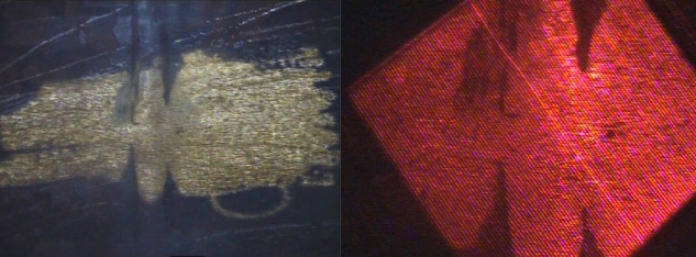
The laser scans were also taken at locations where anomalies with minimal wall loss of 0.09 in (2 mm) or less were detected during the pipe’s initial visual inspection. One such anomaly occurred at 70 ft (21 m) with wall loss of 0.09 in (2 mm), as shown in Figure 6.
The inspection results were analyzed by specialists, and the data were formally presented to the pipeline operator within hours of removing the tool from the pipeline. With the pipeline found to be in good shape, the PS03 system was returned to service.
Contact Aaron Huber, Diakont—e-mail: ahuber@diakont.us.com.
Reference
1 J. Minder, "Robotic In-Line Inspection of Unpiggable Piping on the Transco Pipeline and the Trans-Alaska Pipeline System (TAPS)," NACE Corrosion Risk Conference, paper no. RISK16-8384 (Houston, TX: NACE International 2016).