Natural gas produced from different subsea wells is processed through various stages before entering the pipelines for local markets or export. The production of natural gas from subsea wells is carried out using a subsea “Christmas tree” system that includes various control valves. Hydraulic oil is supplied to different production/control valves through a hydraulic power unit, where pressures range between 21 and 52 MPa.
A circulation pump exists on the hydraulic power unit to transfer hydraulic oil from the storage (backup) tank through filters to the main supply tank. The hydraulic circulation pump has a 2.2-kW motor and can handle 50 L at 1 MPa. The filter replacement program depends on the differential pressure across the filter element. The hydraulic circulation pipeline is made from Type 316L stainless steel (SS) (UNS S31603; ASTM A3121) with a 1-in (25-mm) outer diameter and a thickness of 0.078 in (2 mm). Maximum hydraulic pressure in the circulation pipeline usually approaches 500 kPa. The hydraulic circulation pump is run manually, depending on the supply tank level, and usually runs for one hour every three to four days.
After ~10 years of normal operation, a leak occurred at the discharge of the hydraulic circulation pump. As a temporary solution, a clamp was installed on the leak for 48 h—until that section of pipe was replaced. Then, the leaking pipeline spool was subjected to different nondestructive and destructive examinations for failure analysis.
Investigations
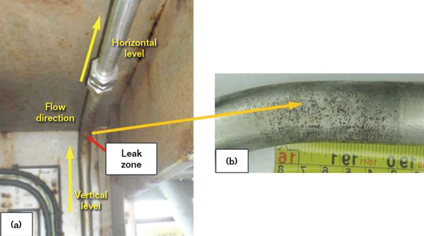
On-site investigations showed that the hydraulic circulation pipeline leak occurred between the circulation pump and the filters at the pipe bend zone between the vertical and horizontal portions of the hydraulic pipeline (Figure 1[a]). Close-up investigation of the outer surface of the pipeline leak showed severe pitting attack (Figure 1[b]); however, no visual indications of a perforation were observed. Away from the leak zone, the outer surface was intact; no external corrosion attack or damage was observed.
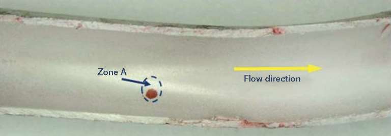
The leaking pipe spool was split longitudinally for close inspection where no internal deposits were found. Dye penetrant testing of the inner surface of the pipeline leak showed indications of a perforation (Figure 2). Except for the perforated zone, the inner surface appeared smooth with no internal corrosion attack. The dye penetrant test showed no indications of internal localized corrosion attack on the face side of the pipeline bend zone. Also, after the dye penetrant test, no indications of internal localized corrosion attack were found along either the vertical or horizontal parts of the failed pipeline spool. Dye penetrant testing showed no indications of cracking either around or away from the leak zone. Except for the perforated/localized attack zone, almost no reduction in wall thickness was found. Wall thickness measurements away from the perforated/localized attacked zone varied between 0.073 and 0.0776 in (1.85 and 1.97 mm).
Specimens from both the leak and non-leak zones were taken for chemical analysis, optical and scanning electron microscopy (SEM) examinations, energy dispersive x-ray (EDX) microanalysis, and hardness measurements. Results of the chemical analysis of the failed location showed that its chemical composition falls within the range specified for ASTM A312 Type 316L SS. Optical microscopy examination of different cross sections taken from both the leak and non-leak zones confirmed that external pitting attack was confined to the leak zone (Figure 3). No significant difference in the microstructure of the leak and non-leak zones was found; a normal austenitic structure for Type 316L SS was observed for both zones with no distinct microstructure abnormalities.
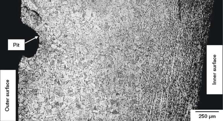
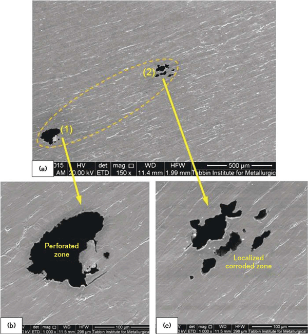
Figure 4 shows SEM photographs with different magnifications of the inner surface of the leak zone (Zone A in Figure 2). In addition to the perforated zone (1), an internal localized corroded zone (2) was found very close to the perforated zone (Figure 4[a]). Higher magnification of the perforated zone showed an irregular pinhole shape with a ~100-µm diameter on the leak zone’s inner surface (Figure 4[b]). A smaller pinhole diameter (~80 µm) was observed on the leak zone’s outer surface. Higher magnification of the localized corroded zone confirmed the existence of localized corrosion crevices/pits with diameters <100 µm very close to the perforated zone (Figure 4[c]). These findings confirm that localized corrosion attack started at the inner surface of the pipeline bend, then progressed toward its outer surface, where pinhole corrosion penetration ultimately occurred.
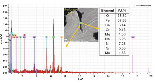
Results of EDX microanalysis of the inner surface of the pipeline’s perforated zone indicated iron and oxygen as its main components (Figure 5). The high concentrations of iron and oxygen indicate the existence of iron oxide as a corrosion product. Except for the perforated zone, SEM examination disclosed no localized corrosion attack at the inner surfaces of either the horizontal or vertical portions of the pipeline.
Hardness measurement surveys of both the leak and non-leak zones were carried out, and the average hardness value of five readings for each zone was recorded. Generally, the obtained hardness values matched those for ASTM A312 Type 316L austenitic SS. The average hardness value of the leak zone (203.5 HV) is higher than that of the non-leak zone (167.5 HV). The higher hardness of the leak zone is related to deformation induced during formation of the pipe bend.
Summary
The failure of the hydraulic pipeline is attributed mainly to internal localized corrosion attack at the root side of the pipeline bend. This appears to be related to crevice and pitting corrosion attack. Crevice corrosion is an electrochemical oxidation process that occurs within localized volumes of stagnant solution trapped in pockets, corners, or beneath a shield (e.g., a sand deposit). Crevice corrosion is highly accelerated if sulfide ions are present in the electrolyte solution. Once a crevice is initiated, even the most benign environments can become extremely aggressive. Crevice corrosion is considered much more dangerous than uniform corrosion, as the corrosion rate can be up to 100 times greater.
Crevices can be created by the existence of fine solid particles, even in small amounts, on the root side of a pipeline bend, particularly under the stagnant or no-flow conditions that occur during an interrupted operation mode. These conditions result in the formation of fine/narrow oxygen concentration cells on the inner surface that eventually lead to pinhole corrosion. Once a pinhole starts, it will continue to progress toward the outer surface.
Pitting corrosion is characterized by localized attack in the form of deep and narrow holes that can penetrate the pipe wall extremely rapidly while the rest of the surface remains intact. Pitting could be initiated at the inner surface of the root side of the pipeline bend as a result of fine inner surface defects that could be created during the bend formation process. Similar to crevice corrosion, pitting corrosion is accelerated during stagnant or no-flow conditions. Both crevice and pitting corrosion can be accelerated by increasing temperature and the presence of chlorides in subsea environments. The pitting attack observed on the outer surface of the leak zone occurred as a secondary effect after the occurrence of the perforation/leak.
Remedial Actions
Repair of the failed pipeline was done by cutting out the leaking segment and replacing it with a new one of the same material but with greater wall thickness. To minimize the possibility of a similar failure in the future, the following recommendations will be considered:
• Using pipeline with a thicker wall, particularly for the bend zone.
• Increasing the pipeline bend’s radius to reduce the possibility of inner surface defects.
• Avoiding solid particles in the fluid.
• Conducting nondestructive inspection on other similar pipeline bends to check for the existence of internal corrosion attack.
Reference
1 ASTM A312/A312M-16, “Standard Specification for Seamless, Welded, and Heavily Cold Worked Austenitic Stainless Steel Pipes” (West Conshohocken, PA: ASTM International, 2016).
Bibliography
ASM Handbook. Vol. 11. “Failure Analysis and Prevention.” Materials Park, OH: ASM International, 1996.
Barer, R.D., and B.F. Peters. Why Metals Fail. 6th ed. New York, NY: Gordon and Breach Science Publishers, 1991.
Brooks, C.R., and A. Choudhury. Metallurgical Failure Analysis. New York, NY: McGraw-Hill, 1993.
Colangelo, V.J., and F.A. Heiser. Analysis of Metallurgical Failures. 2nd. ed. New York, NY: Wiley, 1987.
El-Batahgy, A. “Different Failure Modes at Gas and Petroleum Industries.” International Workshop on Fitness for Service in Chemical Industries, held November 25-27, 2012. Aswan, Egypt.
El-Batahgy, A. “Erosion Corrosion of Oil Heater U-Bends.” MP 33, 4 (1994).
El-Batahgy A. and M. Wheeler. “Localized Corrosion in Condensate Transfer Pipeline.” Pipeline and Gas Journal 239, 3 (2012).
Fontana, M.G. Corrosion Engineering. 3rd ed. New York, NY: McGraw-Hill, 1987.