External corrosion direct assessment (ECDA) methodology is described in the NACE International standard practice SP05021 for integrity assessment of external corrosion threats on buried pipelines. This methodology can be used in combination or separately with NACE SP02042 on stress corrosion cracking (SCC) direct assessment methodology.
The NACE ECDA protocol is a four-step process:
1. Pre-Assessment—Documenting the combination of a pipeline’s physical characteristics, operating history, and prior inspections.
2. Indirect Inspection—Conducting complementary aboveground field surveys like direct current voltage gradient (DCVG), close interval potential (CIP), pipeline current mapping, and soil resistivity measurements.
3. Direct Examination—Exposing the pipe for verification of the aboveground survey results and physical inspection of the pipe coating, pipe surface, and soil electrolyte.
4. Post Assessment—Integrating the results gathered in steps 1, 2, and 3 for overall integrity assessment, validation of the external ECDA process, and determination of the interval period to repeat the ECDA process.
Case History
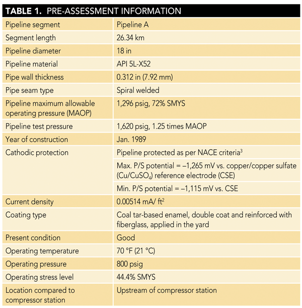
As part of the pipeline integrity assessment program of a natural gas transmission pipeline company, ECDA evaluation was scheduled on an 18-in (457-mm) diameter pipeline in central Pakistan in a high consequence area. As a first step, data collection (pre-assessment) was carried out. The main attributes of the pipeline are listed in Table 1.
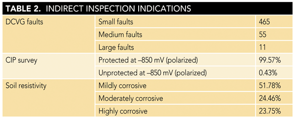
In the second step, field surveys (indirect assessment) were completed and data were collected. The survey data were analyzed through customized software, and direct examination locations were earmarked. Table 2 shows the summary of results obtained.
On the basis of the initial two steps, the third step of visual examination (direct examination) was planned. Table 3 shows the results.
.png)
During indirect inspection data analysis, a large coating fault with low pipe-to-soil (P/S) potential was observed and selected for direct examination. The pipeline was excavated for visual examination. Cracked and disbonded coating with minor rusting and a minor crack on the pipe surface were observed. The soil pH, measured with litmus paper, was found to be 12. In the past, the pipeline operating company had a history of six pipeline failures, all attributed to high pH SCC. The design and operating parameters of previous pipeline ruptures are tabulated in Table 4.
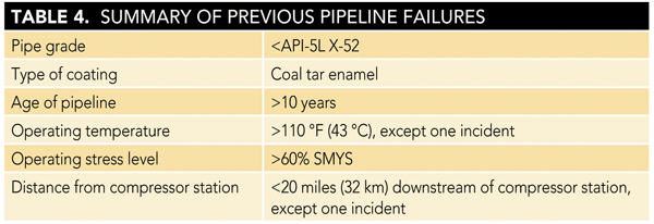
The design and operating data from previous incidents were compared with the data of the pipeline under assessment. It was concluded that the pipeline was under threat of SCC. The operating pressure of the pipeline was reduced immediately to avert any incident of pipeline rupture. The pipeline industry’s applicable standards, NACE SP0204, SP0502, and SP0169;3 and ASME B31.84 and B31.8S,5 were consulted and further assessments were planned.
The further inspections were conducted as guided in NACE SP0204 to verify the presence and depth of the crack:
• Visual inspection
• Ultrasonic inspection
• Dye penetrant testing
• In situ metallography
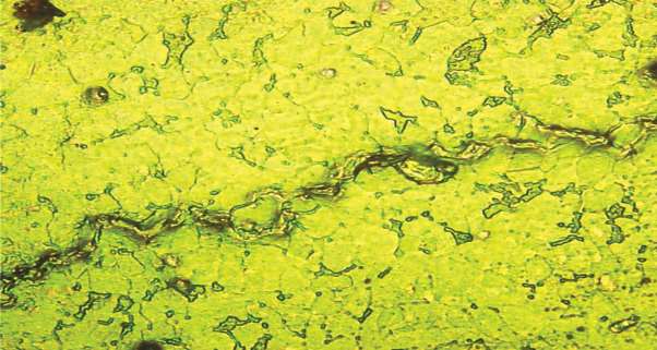
The results of these nondestructive tests (NDTs) revealed the presence of a 4-in (102-mm) long crack at the pipe surface with a depth of 3.6 mm. The photographic records are shown in Figures 1 and 2.

The presence of the crack was verified from the results of the above inspections. Then the pipeline operator decided to validate the results of the NDTs and assess the pipeline integrity by hydrostatic pressure testing in accordance with the guidelines in ASME B-31.8: “For the pipelines in which SCC has been identified, defects may be mitigated by pressure testing to a pressure that will create a hoop stress of at least 100% of the SMYS [specified minimum yield strength] at the high point elevation. The pressure test for SCC shall be held long enough for the test pressure to stabilize, in most cases one half hour or less.”
The hydrostatic testing of the pipeline up to a pressure of 1,803 psig (hoop stress equivalent to 100% of SMYS) was planned and testing started. The pipeline ruptured from the detected crack at a pressure of 1,575 psig (hoop stress equivalent to 87% SMYS), thus validating the assessment made by the direct assessment process. The rupture is shown in Figure 3.
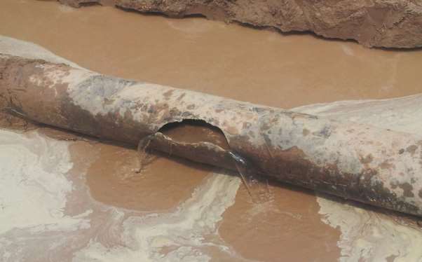
The ruptured portion of pipe was replaced and the pipeline was again hydrostatically tested up to a pressure of 1,803 psig (hoop stress equivalent to 100% of SMYS) for 10 min and at 1,620 psig (1.25 times MAOP) for 24 h. The pipeline was qualified for service and was put into operation.
The success of applying the ECDA methodology was verified, and a high-pressure gas pipeline failure was averted.
References
1 NACE SP0502-2010, “Pipeline External Corrosion Direct Assessment Methodology” (Houston, TX: NACE International, 2010).
2 NACE SP0204-2015, “Stress Corrosion Cracking (SCC) Direct Assessment Methodology” (Houston, TX: NACE, 2015).
3 NACE SP0169-2013, “Control of External Corrosion on Underground or Submerged Metallic Piping Systems” (Houston, TX: NACE, 2013).
4 ASME B31.8, “Gas Distribution and Transmission Piping Systems” (New York, NY: ASME).
5 ASME B31.8S, “Managing System Integrity of Gas Pipelines” (New York, NY: ASME).