For an offshore field with up to 8% hydrogen sulfide (H2S) and 6.5% carbon dioxide (CO2), the choice of material based on calculated corrosion rates had been a corrosion resistant alloy (CRA) material. A design optimization was performed to utilize carbon steel material with fusion bonded epoxy (FBE) coating instead of CRA material.
The reservoir conditions were, however, beyond the conventional limits of FBE coating with respect to partial pressures of acid gases of H2S and CO2. A specialized testing and qualification program using 14 samples (eight samples for pipe body and six samples for girth weld) was performed to qualify FBE coating for high-pressure gas.
A new gas field expansion transports non-associated gas from offshore gas wells through a pipeline to onshore processing plants. The operating conditions for the new gas field are corrosive and exceed the specified conditions for the prevailing approved pipeline internal coatings. The wellhead flowing temperature is 74 °C (165 °F), and the H2S, CO2, and monoethylene glycol (MEG) values are 8% H2S, 6.5% CO2 and 80% MEG.
Earlier coating qualifications for FBE products to protect gas pipelines were based for service up to 49 °C (120 °F), 5% H2S, 8% CO2 and 30% MEG. The temperature, H2S acid gases content, and concentration of MEG are higher for the new gas field.
Consequently, the need to conduct extensive lab testing under the new operating conditions was established to ensure the coatings could withstand the higher temperature, higher levels of H2S acid gas content, and the higher concentration of MEG being injected for hydrate control.
Coating Testing Program
Experimental Procedure
A testing program was developed to establish the suitability of FBE coating for the new gas field, based on the coating service temperature and H2S, CO2, and MEG concentrations. Operating conditions shown in Table 1 were shared with coating vendors and, subsequently, coated panels were requested from paint manufacturers.
The test program was designed to cover the coatings’ physical and chemical properties before and after exposure to the simulated operating conditions in two sets of conditions suited to the gas field conditions shown in Table 1.
For the test program, 14 internal protective coating systems (six main body and eight girth weld coating systems, as shown in Table 2) were assessed under the new gas production operating conditions.
Testing Methodology

The test program included various test methodologies, such as dry film thickness (DFT) testing, hardness testing, holiday detection, pull-off adhesion testing, electrochemical impedance spectroscopy (EIS), and autoclave testing.
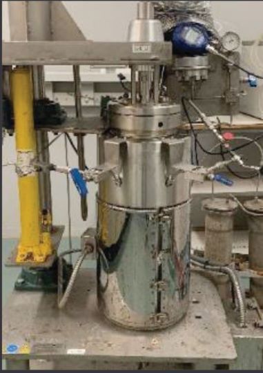
Figures 1 and 2 show the EIS and high-pressure, high-temperature static autoclave vessel. Autoclave testing detects visual damage such as pinholes, cracks, blisters, and change in colors.
During EIS, good coatings will show high impedance values after exposure above 108 Ω·cm, while poor coatings will exhibit impedance values of 107 Ω·cm and below. In a hardness testing, an increase in hardness indicates that the coating exhibited additional curing during exposure.
During adhesion testing, the higher the adhesion strength of the coating, the better the coating resistance to under-paint corrosion.
The high-pressure and high-temperature static autoclave shown in Figure 2 was utilized to simulate the type of service and environment the coating would be exposed to in the field.
Pull-off adhesion tests (ASTM D4541), EIS measurements, hardness measurements (ASTM D2240 Shore Scale D), thickness measurements (ASTM D70914), holiday detection (ASTM G625), and pull-off adhesion tests (ASTM D4541) were carried out on the coated panels before and after exposure.
A pair of standard coating test panels from each type of internal coating system, shown in Table 2 , were exposed in the autoclave reactor at each condition, shown in Table 1 , after passing the preliminary tests (visual examination, holiday, hardness, thickness, adhesion, and EIS).
The coated panels were mounted in the autoclave vessel such that the bottom half of each panel was immersed in the liquid phase, whereas the remaining upper half is exposed to the gas phase in the upper portion of the vessel.
Once the test duration of seven days was complete, the autoclave was opened and the samples were removed from the vessel and visually examined for any clear defects or signs of degradation, blisters (ASTM D714-02), and cracks (ASTM D661−93) before EIS, hardness, thickness, holiday, and adhesion testing were conducted.
Testing Results
The findings from the comprehensive test program showed varying results depending on the type of coating system and its application methodology. A summary of the results is shown in Table 2 , while a detailed coatings performance testing discussion is provided in Reference 1.
Of the six FBE coatings tested for the sour gas test operating conditions, three products passed the test conditions, while three products failed the test conditions. Failure mode for products that failed the test were adhesion failure, severe discoloration, swelling, and hardness reduction.
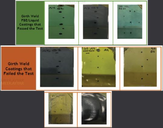
Of the eight girth weld coatings (five liquid and three FBE) subjected to new gas field simulated operating conditions, two FBE coatings and one liquid coating passed the tests, while one FBE coating and four liquid coatings failed the tests. Failure mode for products that failed the test were adhesion failure and blistering.
Conclusion
Initial assessment of prevailing coating standards and coating product datasheets revealed that an internal coating system would not be able to tolerate the operating conditions due to the high presence of H2S and CO2 acid gases and the high concentration of MEG being injected for hydrate control.
The choice of material would be a corrosion-resistant alloy material due to internal coating product limitations and based on calculated corrosion rates from corrosion prediction software.
To optimize the material selection, a testing program was developed to establish the suitability of FBE coating for the new gas field operating conditions, where the coating service temperature, H2S, and MEG were higher than previously known conditions.
Based on the observations and analytical results of the comprehensive coating test program, the following has been concluded:
- Three coating products (FBE coatings) were qualified to protect the pipe main body for service up to 74 °C (165°F), 5% H2S, 8% CO2, and 50% MEG.
- Three coating products (two FBE coatings and only one liquid coating) were qualified to protect the pipe girth weld for service up to 74 °C (165 °F), 5% H2S, 8% CO2, and 50% MEG.
- The pipelines for the new gas field would be internally coated based on the qualification tests, and no cladding was required.
- FBE coating product CS-MB-3 was selected by the project for coating of the main body.
- FBE coating product CS-GW-2 was selected by the project for double-jointing scope of line pipes.
- Liquid coating product CS-GW-6 was selected by the project for internal coating of large diameter bends, and for internal field joint coating offshore while laying the pipe.
Acknowledgment
This work is based on collaborative work carried out by different departments in Aramco.2 Special thanks to the management of Aramco for allowing the publication of the material presented in this article.
References
1 S. Ayyar, “Selection and Testing of Fusion Bond Epoxy Coating for High Pressure Pipelines with H2S and CO2 Acid Gases,” AMPP 2023, paper no.19482 (Houston, TX: AMPP, 2023).
2 “Internal Pipeline Coatings Assessment for New Gas Pipelines,” SAER-10496 Aramco Document.

Editor’s note: This article first appeared in the April 2024 print issue of Materials Performance (MP) Magazine. Reprinted with permission.