This two-part article from experts at Matergenics Inc. (Pittsburgh, Pennsylvania, USA) is a review of the corrosion risk assessment, structural considerations, and engineering solutions for the steel reinforced structural elements within an aging concrete building that exhibited accelerated corrosion in corrosive environments, along with factors that could potentially result in the progressive failure and eventual collapse of an aging building.
Part 1 addresses the fundamentals of structural analysis, rebar corrosion, carbonation, and the role of chlorides. Part 2 will address inspection and condition assessment procedures and recommendations; engineering solutions by coatings and cathodic protection; case histories; and cathodic protection design of concrete rebar with finite element simulations.
Structural engineering analysis is an important part of condition assessment of aging concrete structures. Structural engineers involved in condition assessment need to be informed of the principles and practice of corrosion risks facing aging concrete structures.
The approach toward this issue, from a corrosion engineer’s standpoint, is to perform an inspection/condition assessment before making any judgments or recommendations.
The procedure for this approach starts with a desk study. In this stage, background information such as the structure age, structure design and materials, geotechnical reports, along with geographical and climate data, should be collected and reviewed.
The next step is to plan for a preliminary condition assessment of the structure, which may include a Geographical Information System (GIS) corrosion mapping, followed by visual inspections of the structure and its load-bearing members.
Afterward, various focused tests and condition assessment techniques must be performed to quantify the risks for the aging structure.
Structural Analysis: Retaining Walls and Load-Bearing Beam Ceiling Members
The use of concrete as a structural material can be traced back to 6500 BC, when the Bedouins used a concrete-like substance in building their structures. Throughout the ages, various civilizations have discovered concrete and used it in the building of their cities and structures.
The Romans used concrete extensively in the building of their structures in the Roman Empire. China used a concrete-like substance in the building of its cities and, most notably, the Great Wall. Many of the ancient structures built with concrete have survived today after thousands of years, attesting to the durability of concrete.
Modern portland cement concrete was developed in 1824. Subsequently, continuous refinements to the manufacturing processes have increased the structural strength characteristics, as well as helped ensure consistent quality. In the mid-1800s, steel was introduced as a reinforcing element in concrete.
The characteristics of concrete are like that of natural stone. Concrete is very strong in compression; however, it is weak in tension. Typical concrete compressive strengths are between 17.24 to 27.58 MPa (2,500 to 4,000 psi), while typical tensile strengths are between 2.07 to 4.83 MPa (300 to 700 psi).
Due to its low tensile strength, cracks are a natural characteristic of concrete. When a load is placed on a concrete structure, the portions of that structure that are placed in tension will be susceptible to cracking. These loads include seismic, shrinkage, temperature change, lateral pressure from soil, settlement, and point loads from structural elements.
Although the cracking cannot be prevented, there are ways of minimizing the cracks and the problems that may ensue.
The primary way to control cracking is to add steel reinforcing to the concrete structure. Steel has a high tensile strength. Thus, when added to a concrete structural element, it will carry any tensile stresses that element will experience.
When a normally reinforced concrete element is subjected to tensile forces, the concrete will remain whole until the tensile forces exceed the tensile strength of the concrete between 2.07 to 4.83 MPa (300 to 700 psi).
When the tensile stress of the concrete is exceeded, small cracks will develop. At this stage, the concrete will lose its tensile strength and the steel will resist all the tensile stresses. Thus, all normally reinforced concrete structures will have cracks due to excessive tensile stresses. The exception to this is to use either pre-tensioned or post-tensioned concrete elements.
Generally, concrete cracks with less than 3.2 mm (0.125 in) in width are acceptable and do not affect the strength of the structural member. All cracks should be monitored, and if the crack grows in width or length, long-term structural problems could occur.
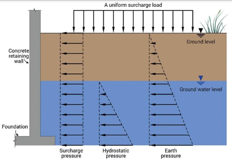
Two of the most common concrete structural elements are retaining walls and beams. Various types of cracks could occur on concrete retaining walls. Vertical cracks could indicate differential settlement of the structure. Vertical and horizontal cracks with bowing of the wall could indicate that the wall is not able to resist the lateral and hydrostatic earth pressures placed on the wall.
Should it be evident that cracks are growing, and the wall is bowing, remediation will be required to ensure long-term stability of the wall. Figure 1 presents a schematic showing earth pressures that could cause cracking in a retaining wall.
Beams are also subject to cracking. Under load, the top of a beam is in compression, so minimal cracking is normally found on the top of a beam. The bottom of the beam is subjected to tension, so cracking is generally found on the bottom of a beam. Tension or flexural cracks are generally vertical cracks that appear on the bottom center of a beam.
 Schematic showing typical cracks in a concrete beam under load. (b) Common configuration of steel rebars for reinforcing a concrete beam.")
Beams may also have shear cracks. These cracks are caused by the vertical load trying to “punch through” the beam. Shear cracks are typically seen as diagonal cracks located near the ends of the beam. Figure 2(a) shows typical cracks in a beam under load.
To provide strength to a beam, steel reinforcement is cast within the beam. Longitudinal rebars are placed at the bottom of the beam to carry the tensile stresses, while vertical rebars are placed throughout the beam to carry the shear stresses. This is shown in Figure 2(b).
Cracks found in beams should be monitored to ensure that the number of cracks and the length of the cracks do not increase. If the number of cracks, crack growth, and excessive deflections are noted, it could be signs that the beam is loaded beyond its designed capacity. Remediation and additional support may be required to ensure long-term and continued service life of the beam.
If cracks occur in a highly corrosive environment, chlorides and other corrosive ions could enter the crack and attack the steel reinforcing. In this instance, corrosion of the steel reinforcing will expand the volume of the steel. This will result in further cracking, with the cracks increasing in width.
In the most severe instances, spalling of the concrete covering the reinforcing bars will occur, exposing the rebars to the corrosive environment. Figure 3 shows a beam that is cracked and deformed due to accelerated corrosion of the rebar and being in an overloaded condition. Severe spalling is also evident on the beam.

Corrosion of the rebars will reduce the steel diameters of the rebars. The reduction in diameter will result in reducing the strength of the rebars. The reduction in strength of the rebars will result in a lowered ability of a structural element to resist the loads placed upon it. This will result in additional cracking and deflection. Unless work is done to remediate this condition, the cycle will continue until failure of the structural element occurs.
As a rough guide, the reduction in strength can be calculated by comparing the usable area of the rebars once all the corrosion elements are removed with the original area of the rebars. For instance, consider a #4 rebar. A #4 rebar has a cross-sectional area of 129 mm2 (0.2 in2).
If a corroded #4 rebar was found and after the corrosion products were removed, the cross-sectional area was calculated to be 96.77 mm2 (0.15 in2), and that would represent a reduction of 25% from the original cross-sectional area. Thus, it can be inferred that a 25% loss of strength has occurred due to corrosion.
The assessment of any foundation walls and beams should include the use of laser imaging, detection, and ranging (LiDAR) technology. Deformations of a wall or beam can easily be assessed and qualified using LiDAR. The LiDAR scan will also set a baseline condition from which subsequent scans can be compared. This will provide an indication if a wall or beam is deflecting over time or if any deflections have stabilized.
In a recent case, the authors observed accelerated corrosion of steel reinforcement, as well as deflection and bowing of a retaining wall, in a basement of a large industrial building. LiDAR survey and structural inspection revealed that the deflection is due to construction of a heavy smokestack and lateral earth pressure of soil in vicinity (152.4cm (<5 ft)) of the retaining wall.
Earth pressure refers to the pressures caused by the weight of soil and ground water and surcharge pushing against slabs and foundations, particularly against underground concrete blocks or poured concrete wall foundations. Lateral earth pressure forces the wall to bend inward, as shown in Figure 1, creating a crack in the foundation wall.
Rebar Corrosion
 ingression of chloride ions (b) corrosion of rebar and loss in thickness of rebar (c) generation of voluminous rebar corrosion products and (d) spalling of concrete.")
Rebar corrodes in the presence of chlorides, which are common in sea water and deicing salts. Corrosion of rebar can cause reduction in cross-sectional areas, as seen in the photographs. This loss of thickness can weaken the rebar and cause collapse.
Delamination is caused by the formation of iron oxide around the rebar, which results in the expansion in volume of the corrosion products causing the concrete to spall. This eventually leads to cracking or sections of concrete breaking away from the rebar. It is observed where the iron oxide was building up at the brown/black line. Another way that corrosion of rebar can cause concrete failure is through carbonation, delamination, or spalling.
The salt slowly permeates the concrete and corrodes the rebar, reducing the thickness of these critical support structures over a period of years. For aging reinforced concrete, the process is decades in the making and is presented in Figure 4.
Figure 5 (top image) is a close-up photograph of the rebar inside core sample with thickness loss shown at the top. The corrosion risk was captured early on. Corrosion mitigation and cathodic protection prevented catastrophic failure in this 100-year-old building.
Carbonation
In older concrete structures, carbonation occurs at the exterior surfaces. The process of carbonation will cause the carbonated surface layer to shrink and crack. Cracks from carbonation tend to be shallower than cracks from initial drying shrinkage. Carbonation can be detected by pH measurement.
Synergistic Effects of Carbonation and Chlorides
The chloride content at the carbonation front has reached higher levels than in uncarbonated concrete and can be much higher than the levels measured just below the concrete surface. This increases the risk of corrosion initiation when the carbonation front reaches the reinforcing steel.1
The decrease in pH of the carbonated concrete also increases the risk of corrosion because the concentration of chlorides necessary to initiate corrosion, i.e., the threshold value, decreases with the pH. This is because the chloroaluminates break down, freeing the bound chlorides as the pH drops.
Conclusion
Corrosion risk assessment of aging concrete structures should include analysis of load conditions for potential cracking, vibrational issues, rebar corrosion, carbonation, and chloride-induced corrosion.
It is critical that condition assessment should include both structural engineering as well as corrosion engineering analysis. Structural engineers must therefore work closely with corrosion engineers in this endeavor.