Often reinforced concrete requires patch repair when an isolated severe corrosion incident arises. The need for concrete repair is most often due to corrosion of the reinforcing steel. Concrete, when exposed to chloride, can develop severe corrosion, requiring a repair.
Typically, this involves the removal of the corrosion-containing concrete, replacing the rebar (if needed), and filling the hole with a cementitious substance. Corrosion can then become high in areas surrounding the patched portion when steel in the patch becomes a cathode to steel in surrounding areas. This occurrence is commonly referred to as ring corrosion.
Scientists are using sacrificial anodes to significantly reduce the acceleration of corrosion in these patched concrete areas. The steel, both in the patch and surrounding it, is afforded corrosion control thanks to the sacrificial anodes, which are inserted into the patch.
A study was conducted by Neal S. Berke and Kristin M. Ade with Tourney Consulting Group, LLC (Kalamazoo, Michigan, USA), along with Brad Nemunaitis and Walter Hanford with The Euclid Chemical Company (Cleveland, Ohio, USA). Their objective was to evaluate the performance of high-current output, zinc-based embedded sacrificial anodes using the Bureau of Reclamation M-82 “Standard Protocol to Evaluate the Performance of Corrosion Mitigation Technologies in Concrete Repairs.”1
Topically applied surface treatments and patch repairs, with and without the use of sacrificial anodes, are described in this standard. The scientists used this test to determine the effectiveness of embedding sacrificial anodes to lessen the corrosion of steel on areas surrounding the concrete patch. Details of the study are presented in CORROSION 2019 paper no. 13097.2
Until recently, a standard did not exist by which to evaluate certain corrosion mitigation technologies, causing difficulty. Determining methods needed or materials required for repair from an engineering standpoint was unclear, especially because comparing other corrosion-prevention technologies might be inaccurate. The M-82 protocol called for large reinforced concrete slabs, representative of what is found in the field.
Ten large steel-reinforced concrete samples were used that were 40 x 40 x 5.5 in (1 x 1 x 0.14 m) in dimension; five were test specimens and five were control specimens. The researchers chose this particular size because the large surface area allowed them to evaluate anode-throwing power. In addition, the specimens were small enough to be placed on shelves and transported with a forklift. A ready-mix truck supplied the concrete.
Figure 1 shows a schematic of the testing samples. As shown, eight reinforcing bars were used, and wire mesh provided the main cathode steel cell for a macrocell between the top and bottom bars. To speed up the corrosion process, cover was reduced in one portion where bars of half-length were placed. Because corrosion occurred earlier in this location, this is where the patch was placed, including sacrificial anodes attached to the reinforcing bars.

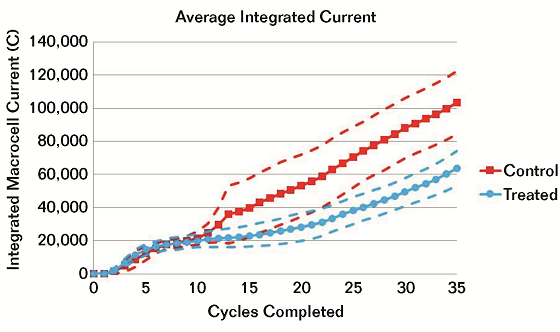
Figure 2 shows the integrated corrosion current average throughout the testing. Initially, the corrosion increased quickly, then it slowed. At that time, the researchers disconnected the two highly corroding bars within the patch, causing corrosion to begin outside the patch.
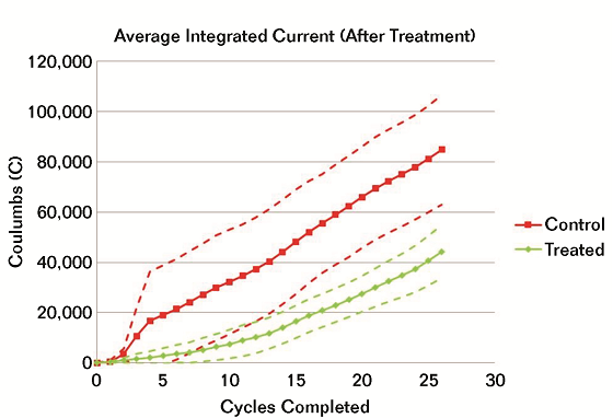
To better compare the performance of the sacrificial anodes, the researchers observed the total corrosion after the repair patch. Figure 3 shows that specimens with sacrificial anodes experienced less than half the corrosion damage of the control specimens two cycles after the confidence limits did not overlap. By the end of the testing, it was half the amount of the controls. Furthermore, analyzing the potential maps before and after the repair helped reveal anode performance.
To determine the mass loss on the anodes, the researchers calculated the anodic currents between the anodes and the rest of the bars, as well as the steel mat. They found the mass loss rates to be higher early on and evened out over time, although they were still increasing. No significant difference in chloride values was indicated between the control and the treated specimens, as expected based on the M-82 testing protocol. The high chloride content at the end of testing (13.5 lb/yd3) highlights the severity of the test.

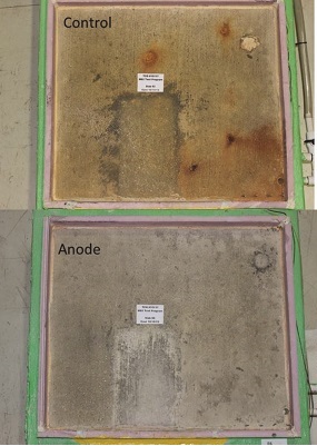
As a result of this study, the researchers found that the slabs with sacrificial anodes had less than half the corrosion activity of the control slabs (Figure 4), which met the requirements of the M-82 standard. Also, after three years of accelerated corrosion conditions, the anodes were still producing current.
 The researchers did have some recommendations for modifications to M-82. Patches should be repaired when patch bars reach 10,000 Coulombs and the bars should not be disconnected from other bars before repair. This would eliminate the requirement for 2,500 Coulombs outside the patch. Minimizing the corrosion that occurs before making repairs better indicates how well the sacrificial anode protects bars outside the patch area.
References
1 M-82, “Standard Protocol to Evaluate the Performance of Corrosion Mitigation Technologies in Concrete Repairs” (Denver, CO: US Bureau of Reclamation, 2014).
2 N.S. Berke, et al., “Evaluation of Embedded Sacrificial Anode Probe for Use in Concrete Repair,” CORROSION 2019, paper no. 13097 (Houston, TX: NACE International, 2019).