The costs associated with broken water mains are rising. As this infrastructure ages, the investment necessary for repairs and replacements increases. It is estimated that the United States should spend over $1 trillion on underground water infrastructure work over the next 25 years, and $1.7 trillion over the next 40 years.
Water main breaks lead to extensive costs and make up a significant portion of municipal budgets due to repair costs, flood damage, loss of revenue for those companies impacted, and the disruption to essential public services like health care or fire protection.
Issues arise when ductile iron (DI) pipe makers claim a 100+ year lifespan, yet research indicates the average lifespan to be about 50 years. To make matters worse, in several water main projects conducted by researchers Mehrooz Zamanzadeh, Edward Larkin, Peyman Taheri, Alyson Char, Aaron Ulmer, Erik Lahti, and Anil Kumar Chikkam with Matergenics Inc. (Pittsburgh, Pennsylvania, USA), service life was a mere 20 to 30 years.
Water main breaks are often attributed to design flaws, incorrect installation, water hammer, soil movement, etc. Because they appear healthy leading up to a failure, the corrosion can be overlooked. Corrosion in water mains is caused by several factors, including crevice corrosion, pitting corrosion, surface corrosion, stray current, microbiologically induced corrosion, galvanic action, and graphitic corrosion (the most common cause).
This article, based on CORROSION 2021 paper no. 16837 by Zamanzadeh et al., examines three case studies in which water mains have failed and focuses on failures due external corrosion.
Case Study 1
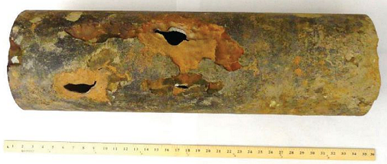
The catastrophic failure of a cast iron pipe led to the flooding of several blocks. The 36-in (91.44-cm) diameter cast iron (CI) water main was about 90 years old. Visually, the pipe appeared to have a large section broken out (36 inches [91.44 cm] long and 18 inches [45.72 cm] wide) from which the water was leaking (Figure 1). 
The researchers tested for the presence of stray current. Normally, corrosion caused by stray current is more severe than that caused by soil. Because stray currents, which can enter a pipe in one location and exit in another (the point at which severe corrosion then occurs), can contribute to external corrosion of a pipe, it is necessary to ascertain its presence. In this case study, there was no evidence of stray current.
Soil samples were taken and tested onsite and in the laboratory. Onsite measurements showed that the soil around the pipeline to be corrosive. Laboratory testing confirmed this and showed the soil had low pH, low soil resistivity values, and moderately high chloride content.
The scientists used a scanning electron microscope (SEM) with an energy dispersive x-ray fluorescence spectrometer (EDS) to test soil sample number 2 because it had the lowest resistivity of the five samples. Elemental composition discovered the sample was probably a slag with high carbon content.
X-ray diffraction found that silica (SiO2), muscovite (KAl2[AlSi3O10][F,OH]2), kaolinite (Al2Si2O5[OH]4), microcline (KAlSi3O8), albite (NaAlSi3O8), clinochlore ([Mg5Al][AlSi3]O10[OH8]), hematite (Fe2O3), calcite (CaCO3), mullite (Al6Si2O13), magnetite (Fe3O4), and gehlenite (Ca2Al[AlSiO7]) were all present in the five samples.
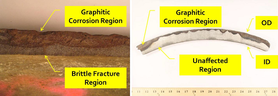
And microbiological analysis proved that all five soil samples were positive for low nutrient bacteria, iron related bacteria, anaerobic bacteria, acid producing bacteria, and sulfate reducing bacteria. Laboratory visual examination (Figure 2), chemical analysis, and metallographic examination of the pipe were also performed.
In Case Study 1, graphitization reduced the wall thickness of the pipe by about 70% in some areas. Corrosive soil in contact with the pipe, leading to graphitic corrosion, caused the failure of the water main. 
Case Study 2
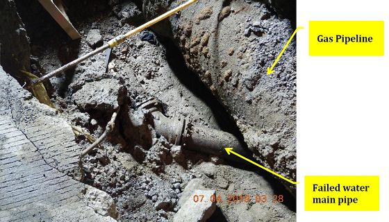
This failed DI water main was repaired with a stainless steel patch in a location that had leaked in the past and had failed to seal it properly. The pipe was 20 years old and 8 in (20.32 cm) in diameter. It crosses under a cast iron gas pipeline on a 45 degree angle. Visual examination showed a leak to the water main pipe under the gas pipeline (Figure 3), along with three additional leaks to the pipe on the same street at different locations. Inspectors noted that the failed pipe sections were removed, and two new sections were installed.
Onsite potential measurements showed considerable fluctuations at all three pipe connections and the presence of stray current was indicated. It is important to note that cathodic protection is the only means of corrosion control on the new water main pipe section. Sacrificial anodes were used and, as the new path of least resistance, degrade faster than the pipe itself. This protects the pipe from having to be repaired, and instead, the anodes can be replaced as needed.
Three soil samples were taken (below the failed pipe section at the leak, at the bottom of the old pipe section that is intact, and the top of the old pipe section that is intact). Laboratory investigation concluded that the first soil sample was corrosive as it contained high chloride and sulfate content and had low resistivity values. EDS data concluded that chlorine was present at the perforation along with other elements and that ion transfer was in process. The researchers note that stray current is existent.
Graphitic corrosion was the primary cause of failure in Case Study 2. The DI water main showed significant loss of wall thickness at the point of failure. The root cause of the failure was due to DC stray currents, corrosive soil, and the synergistic effect of both corrosion mechanisms. 
Case Study 3
Researchers sought answers for the three additional leaks found on the same water main from Case Study 2 (Figure 4). A hole in the top side of the pipe caused the failure. Copper alloy service piping was found near the perforation of the pipe and a cast iron gas pipeline was 3 ft (7.62 cm) from the failed water main pipe and running parallel to it.
Five soil samples (backfill, next to leak, on top of gas pipe, at the leak, and below the pipe) were analyzed in the laboratory. Samples 3 and 5 were very corrosive because of low soil resistivity values, high chloride contents, and high linear polarization resistance corrosion rates. The sulfate content was high in samples 1 and 3. Stereoscopic examination and microexamination were also performed.
The primary cause of the failure of the DI water main was deemed to be galvanic corrosion. Corrosion was only seen around the copper service line that was connected to DI pipe without insulation. The perforation was close to a tapping ferrule. 
The scientists believe the mechanical damage of the PE sheet at the copper service line connection could have permitted ingress of water and soil in between the PE sheet and DI pipe around the copper service line fitting leading to galvanic corrosion. Cathodic protection is recommended as a means of corrosion control in this case.
Recommendations
The scientists recommend a corrosion program as a fail-safe system. This approach to corrosion risk assessment and corrosion mitigation of a water main should include a pre-assessment stage, an indirect assessment stage, and a direct assessment stage.
This article is based on CORROSION 2021 paper no. 16837, presented virtually.