Electric transmission tower foundations have a great impact on the stability and performance of the towers. Without having sound and safe foundations, these structures cannot perform the functions for which they are designed. Reinforcing steel bars (rebar) in concrete foundations for power transmission towers also act as the ground electrodes during current faults.1
Corrosion assessment, lifetime estimation, and corrosion protection of concrete structures are very important issues in corrosive areas. As an example, Iran operates more than 125,908 km of overhead power transmission and subtransmission lines (>63 kV).2
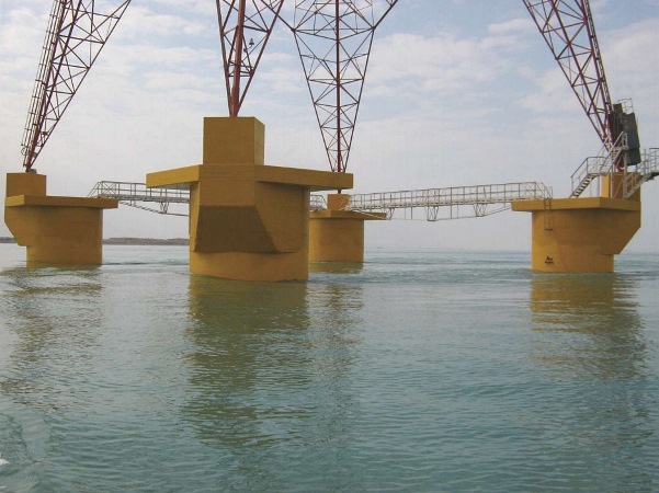
Approximately 19% of these high-voltage lines are located in corrosive coastline environments (Figure 1). Around 17% of these high-voltage lines are more than 30 years old.3 Operation of power transmission lines is controlled by regional electric power companies. One of the companies, Hormozgan Regional Electric Co., spends more than US $400,000 annually to repair and rehabilitate nearly 1,000 corroded tower foundations.4
Corrosion and Cathodic Protection of Steel in Concrete
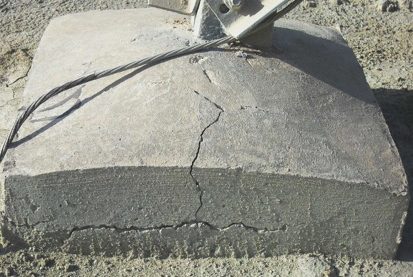
When chlorides reach the steel surfaces inside reinforced concrete structures, active corrosion leads to the formation of expansive corrosion products, resulting in cracks of the concrete cover. It takes only a small amount of corrosion metal loss (e.g., ~0.1 mm) at the rebar surface to create corrosion products sufficient to generate internal stresses that crack the concrete (Figure 2).5
Cathodic protection (CP) is the most effective method of controlling ongoing corrosion in reinforced concrete structures. By applying cathodic polarization, the corrosion potential is shifted to the region of immunity in the Pourbaix diagram; and corrosion is stopped from a practical point of view.6
The application of CP to a reinforced concrete structure transforms the environment around the steel reinforcement over a period of time. The metal surface becomes negatively polarized, thus repelling chlorides; oxygen and water are consumed; and hydroxyl ions are generated at the metal surface. The hydroxyl alkalinity restores the pH at the metal surface, inducing passivity of the metal.7
Investigations
Evaluations were conducted on 152 selected electric transmission tower foundations located along Persian Gulf coasts.
A variety of parameters were measured for corrosion assessment. These parameters included effects of the environmental conditions, as well as the concrete’s structure and properties, on the degree of damage caused by steel corrosion.
During this investigation, NACE SP0308-20088 guidelines were followed. After checking the repair history and visual inspection, data on each foundation were collected for the following parameters:
• Age
• Distance from sea
• Height above the sea level
•
Concrete cover depth
• Rebar diameter
• Alkalinity
• Chloride ion concentration
• Concrete homogeneity and compressive strength
• Soil resistivity
• Corrosion potential
• Corrosion current density (CD)
• Concrete electrical resistivity
Alkalinity (pH) and chloride ion concentration were determined from concrete powder obtained by drilling three 30-mm diameter holes, each 25-mm deep. Alkalinity and chloride content values were obtained by averaging the values of three tested samples. According to ASTM C1218-15,9 water-soluble chloride content is used as an applicable parameter related to corrosion occurrence.
The concrete homogeneity and strength were estimated using the Schmidt hammer. The values for cement content and water/cement ratio were obtained from design documents. Since water content in the mix design is a significant parameter affecting structural durability, it was also obtained from design documents and considered in the evaluation.
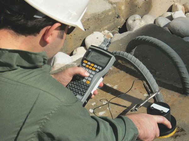
Soil resistivity and corrosion potential were field-measured according to ASTM G57-0610 and ASTM C876-09,11 respectively. The galvanostatic pulse method was used to measure corrosion CD and resistivity of the concrete (Figure 3).
The average temperatures and relative environmental humidity are similar throughout the locations investigated, so the influence of these parameters on the rebar corrosion was not considered.
Results
Table 1 shows typical results for one of the selected foundations. The data for each parameter were then analyzed and 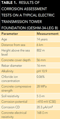 processed by software developed in-house based on an artificial neural network. This software classified the examined tower foundations into one of four corrosion risk categories (low, medium, high, and very high). The results showed ~60% of the selected foundations were placed in either the high or very high corrosion risk groups.
In addition to using sacrificial anode CP systems with the foundations’ patch repairs, the owner of the high-voltage power lines and towers decided that CP systems would also be used for newly installed foundations, which was the first time this was done in Iran. This type of CP, called cathodic prevention, applies to new structures, which are expected to become contaminated by chlorides during their service life, as well as in-service structures with chloride ions that have not reached the steel and depassivation has not yet occurred. The distinction in these terms relates to the historical practice of applying CP primarily as part of the repair/ retrofit strategy after corrosion has been initiated. Cathodic prevention is a proactive approach.
Applying Cathodic Prevention
Cathodic prevention CD is approximately one order of magnitude lower than the typical requirement for CP. This, in part, is because the steel/concrete potentials required for cathodic prevention are less negative than those required for CP. Furthermore, passive steel is more easily polarized.
For this project, the CD was assumed to be 2 mA/m2 for the steel. Since the surface area of the steel in each foundation is 2 m2, the required current is 4 mA. The necessary weight of the anode material, which includes utilization and efficiency factors, was calculated using Faraday’s law, Equation (1):
W = (ARC * CR * L) / (E * U) (1)
where ARC is the average required current (0.004 A), CR is the consumption rate of the anode (11.2 kg/y for zinc), L is the designed lifetime (20 years), E is efficiency (0.9), and U is the utilization factor (0.85). The calculated weight of zinc is 1,200 g, which is provided by four 300 by 50 by 10 mm discrete galvanic anodes, each containing ~300 g of pure zinc (Figure 4[a]).
The zinc sacrificial anodes were embedded in a chelation material, which forms molecules with the metal ions.
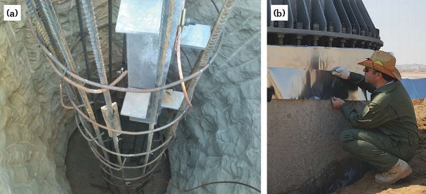
Seventy-two foundations were protected by the cathodic prevention method. To assess performance of systems in the region, cathodic prevention by zinc sheet anodes was also applied on one of the foundations using anodes from the same producer (Figure 4[b]). After one month of operation for the cathodic prevention, the initial performance of the systems was checked according to ISO 12696:2012.12 The results of this evaluation at three different test points indicated that 100-mV potential decay from the instant-off value was achieved within 24 h after opening the circuit.
Conclusions
• The preliminary investigation indicated that roughly 60% of power transmission tower foundations in the north part of the Persian Gulf needed to be protected against chloride-induced corrosion. Hence, CP was the appropriate and logical approach to protect these concrete foundations and prolong their useful lives.
• Cathodic prevention for new foundations was applied using distributed hydrogel and strip-type galvanic systems. After one month of operation, potential decay from the instant-off potential confirmed the effectiveness of the applied system.
Acknowledgements
The authors would like to thank the Hormozgan Regional Electric Co. and Takta Sharif Corrosion Co. for their commercial and financial support. The contribution of Ehssan Gheirati for his review and editing of this article is greatly acknowledged.
References
1 V. Brandenbursky, et al., “Ground Resistance Calculation for Small Concrete Foundations,” Electric Power Systems Research 81 (2011): p. 408.
2 “Electric Power Industry in Iran 2013-2014,” Tavanir Holding Co., report no. 11-11, October 2014.
3 “Statistical Report on 47 Years of Activities of Iran Electric Power Industry,” Tavanir Holding Co., report no. 9-11, October 2014.
4 “Installation of Cathodic Protection System on 5 km Foundations of 230 kV Electric Transmission Line Towers,” Takta Sharif Corrosion Co., report no. 94-084, January 2016.
5 M. Dugarte, “Polarization of Galvanic Point Anodes for Corrosion Prevention in Reinforced Concrete” (Ph.D. diss., University of South Florida, 2010), p. 8.
6 I. Martinez, C. Andrade, “Application of EIS to Cathodically Protected Steel,” Corros. Sci 50 (2008): p. 2,948.
7 C. Christodoulou, et al., “Assesssment the Long Term Benefits of Impressed Current Cathodic Protection,” Corros. Sci. 52 (2010): p. 2,671.
8 NACE SP0308-2008, “Inspection Methods for Corrosion Evaluation of Conventionally Reinforced Concrete Structures” (Houston, TX: NACE International, 2008).
9 ASTM C1218-15, “Standard Test Method for Water-Soluble Chloride in Mortar and Concrete” (West Conshohocken, PA: ASTM International, 2015).
10 ASTM G57-06, “Standard Test Method for Field Measurement of Soil Resistivity Using the Wenner Four-Electrode Method” (West Conshohocken, PA: ASTM, 2006).
11 ASTM C876-09, “Standard Test Method for Corrosion Potentials of Uncoated Reinforcing Steel in Concrete” (West Conshohocken, PA: ASTM, 2009).
12 ISO 12696:2012, “Cathodic Protection of Steel in Concrete” (Geneva, Switzerland: ISO, 2012).