Editor’s note: Learn more about cathodic protection for steel structures buried in soil in this new Materials Performance quarterly special feature, “The Science Behind It.” After you’ve read the MP article about protecting underground steel grillage power transmission tower foundations, explore the science behind the corrosion problem, which is presented in several related CORROSION articles listed at the end of the article.
Underground corrosion of structures supporting power transmission and distribution (T&D) lines is the primary cause of in-service equipment degradation. Each year, utility companies allocate increased corrosion mitigation budgets to refurbish a large population of aging and corroded structures. Accordingly, effective and economically feasible corrosion mitigation techniques, such as cathodic protection (CP) systems specifically designed for T&D structures, are in great demand.
Widely used conventional CP design methods are based mainly on empirical formulas and designer experience. Such design methods, although very useful, were primarily developed for piping systems and are not optimal for structures with more complex configurations. They fail to incorporate all design factors and often require the use of relatively large safety factors. To address this issue, an electrochemical simulation tool was developed for designing efficient CP systems for buried components of transmission structures. Grillage-type foundations were selected to highlight some capabilities of the proposed approach because these types of foundations are common in transmission structures, and their geometrical irregularities (e.g., edges, holes, bends, and joints) pose a recognized CP design challenge that requires further investigations.
Steel Grillage Foundations
Transmission tower foundations are required to stabilize the towers by transferring the structural loads to the underground environment. They must be designed to resist movements such as settlement, uplift, and lateral displacement.1
Among different types of foundations, steel grillage foundations are the preferred choice for four-legged lattice towers when footing conditions allow their application. Grillage foundations include a horizontal grillage base plate constructed from structural steel (usually galvanized angles, beams, and channels), and some vertical members, which are extensions of a tower leg. Common grillage foundation configurations that connect the tower leg to the grillage plate include pyramid supports, a single tubular member, and a single leg stub.
The main advantages of grillage foundations are their low cost and ease of installation. They are entirely shop-fabricated and typically can be purchased with the tower. Furthermore, grillage foundations require minimal installation time and allow immediate tower assembly. They usually do not need a concrete pour, so concrete-related transporting and curing time is not required.2
The major drawback of grillage foundations is the necessity of relatively deep excavations for their installation. Sometimes, due to variations in soil environments along the power line route, tower foundations need to be enlarged by pouring a concrete base around the grillage if actual soil conditions are not as good as those assumed in the original design. In addition, large grillages are difficult to set and require accurate adjustments for tower installation.2
Cathodic Protection Model
The primary goal of the proposed CP design tool is to determine detailed distribution of potential and current density (CD) on the surfaces of grillage foundations. Such information allows examination and optimization of the anode bed design so the structure can be sufficiently polarized in accordance with the NACE International criteria for CP.3
Three-Dimensional Geometry Model
Since CP is a geometry-related matter, inclusion of more details in the geometry leads to a more accurate design. Three-dimensional (3-D) geometry models for grillage foundations are used in CP modeling. Such detailed geometry models enable accurate calculation of the total surface area and allow precise predictions of under-protected and overprotected areas.
The surface area for grillage foundations varies from ~60 ft2 (~6 m2) to ~260 ft2 (~24 m2) depending on the size and design of the grillage plate.

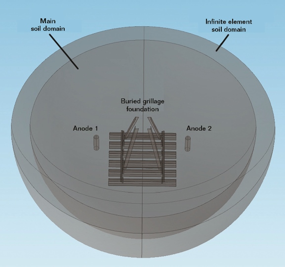
A soil hemisphere with a radius of a few feet is considered the main soil domain for electrochemical simulations. Another soil domain, which surrounds the main soil domain, accounts for the effects of the infinite soil environment. In Figure 1, a sample computational soil domain is depicted.
Input Data: Field Survey and Lab Tests
For the sake of modeling accuracy, certain tests must be performed to characterize the soil environment and collect relevant electrochemical data. These include:
• Soil resistivity test
• Soil-to-structure electrochemical potential test
• CP current requirement test
• Voltammetry tests
While the first three tests must be performed on-site, voltammetry tests require laboratory facilities.
Soil resistivity measurements can be performed either on-site or in a laboratory per ASTM G1874 and AASHTO T2885 standards. It is recommended, however, to use the Wenner four-pin method, ASTM G57,6 to perform in situ soil resistivity tests, which allows identification of soil layers, if any. Since distribution of protection current in soil environments strongly depends on the soil resistivity, the presence of soil horizons with different resistivity values can make a considerable difference in the performance of a CP system.

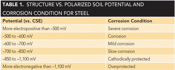
Based on field experience, the electrochemical potential of a directly buried structure, measured with respect to a reference electrode (e.g., copper/copper sulfate [Cu/CuSO4] electrode [CSE]), indicates the corrosion condition, as listed in Table 1.7 Note that this potential and the corrosion rate will change during different seasons mainly due to variations of soil temperature and moisture content.
The required current to cathodically protect a grillage foundation can be measured on-site by the current interruption technique, which uses temporary anodes and a portable direct current power supply. Based on soil resistivity and bare surface area at the foundation, the required current may vary from a few mA to a few hundred mA. Where CP current requirement tests are not possible, the required current can be estimated from Table 27 once the bare surface area is calculated/approximated.

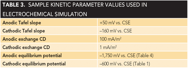
Anodic and cathodic Tafel equations were used to model electrochemical processes at the surfaces of sacrificial anodes and steel structures (cathodes). This required laboratory voltammetry tests to evaluate the relevant kinetic parameters (i.e., exchange CD and Tafel slopes for anode and cathode materials at a sample soil collected at the tower footing).8 The kinetic parameters can vary with factors such as soil resistivity, pH level, oxygen concentration, metal ion concentration, surface area of electrodes, temperature, chloride contamination, and organic matter content.
Examples of values for kinetic parameters are listed in Table 3. The listed coefficients are provided for demonstration purposes—considerably different values may be obtained in different soil environments.

System Selection and Primary Calculations
In contrast to pipelines, which are continuous structures with large surface areas, foundations of T&D towers are separate structures with relatively small surface areas. Accordingly, it is preferred to install individual galvanic CP systems for each tower and implement the same for each tower within a group that share common characteristics.
Magnesium and zinc anodes are generally recommended for soil application; nonetheless, use of zinc anodes is suggested only for low soil resistivity conditions.

High-potential magnesium alloy anodes (Type M1, per ASTM B8439) were selected for the example (Table 47). The required capacity of the CP system (QCP) can be calculated from Equation (1):

where ICP (A) is the required protection current obtained from on-site testing or approximated from Table 2. A minimum life of 20 years is considered for the CP system. Once the capacity of the CP system is determined, the minimum mass of the anode (mMag) for the system can be calculated from Equation (2):

where QMag (A-y/kg) is the theoretical capacity of anode material, E is the current efficiency, and U is the utilization factor, as listed in Table 4.
In general, CP systems with distributed anodes provide lower anode-bed resistance and better protection coverage for foundations with irregular geometries; but the cost for excavation and installation is a limiting factor. The objective of the proposed CP design method is to compare different anode arrangements to find an optimum design in terms of cost and performance.
Numerical Analysis and CP Design Optimization
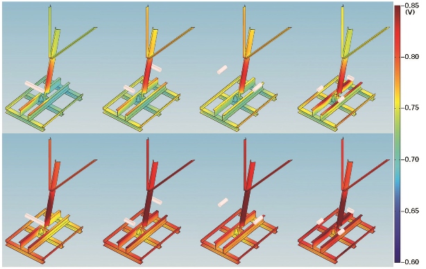
A finite element solver, COMSOL MULTI PHYSICS† (Version 5.2), was used to solve the governing electrochemical equations. In this example, CP simulations were developed for a foundation with a single leg stub. Two brace angles of the structure are also partially buried (Figure 2).

In this example, the foundation is uncoated and buried in a neutral soil with a resistivity of 5,000 Ω-cm. From the 3-D geometry model, the buried surface area is calculated as 70 ft2 (6.5 m2).
Current requirement tests in neutral soils indicate that 37 mA would be required for CP of the buried members. Alternatively, the information in Table 2 can be used to estimate the required current. After using Equations (1) and (2), the minimum mass of magnesium anodes for 20 years of CP in neutral soil can be calculated as 15.3 lb (7 kg). Cylindrical 5, 9, and 17 lb (2.3, 4, and 7.7 kg) magnesium anodes were considered for CP modeling. Accordingly, anode beds with one 17-lb anode, two 9-lb anodes, or three 5-lb anodes were selected to investigate different CP design scenarios.
In Figure 2, simulation results for different CP system designs are shown. Four different anode bed designs with horizontal anodes are presented in each row. Results in the top row correspond to neutral soil with soil resistivity of 5,000 Ω-cm. To illustrate the effects of soil resistivity on CP performance, simulation results at a slightly acidic soil with a resistivity of 2,000 Ω-cm are presented in the bottom row. To provide a fair comparison between these cases, the anode size is the same. The required CP current obviously increases as the soil corrosivity increases, which in turn increases the required mass for anodes for a certain CP system life.
Distribution of polarized potentials on buried surfaces of the foundation was investigated to assess the performance of each anode bed design. According to the NACE standard,3 a minimum surface potential of –0.850 V vs. CSE is required for CP of steel (Table 1). In Figure 2, dark-red areas are protected portions of the foundation, while orange, yellow, green, and blue areas, in that order, represent surfaces with decreasing levels of protection. The results show that anode beds provide better protective current distribution in soils with lower resistivity and that highly distributed anode beds provide more uniform coverage.
Only a few anode bed designs are discussed here; but the design tool allows investigation of various designs, and its high-resolution results provide the basis for sound decisions.
Conclusions
These simulations confirm that areas with geometric features (corners and edges) located in the vicinity of anodes receive the maximum protective current while flat surfaces, particularly when shielded, are least polarized/protected. As a result of geometrical complexities, multiple anodes for CP of the grillage foundation are required. Furthermore, in soils with high resistivities, it is necessary to consider a greater number of anodes buried close to the structure (≲2 ft [0.6 m] away) to achieve a good level of protection.
For large grillage foundations, horizontally buried anodes are preferred to protect the horizontal members of the grillage, while vertically buried anodes are recommended for protection of vertical (leg) components. Nonetheless, it is always recommended to provide full CP to critical load-bearing members of the foundation—usually the legs—thus, a combination of vertical and horizontal anodes might be required.
For galvanized structures, the equilibrium potential of the structures gradually shifts toward electropositive values as the zinc layer is consumed and corrosion progresses into the steel substrate. Accordingly, the design of CP systems for two identical galvanized foundations in the same soil environment depends on their age and the quality of the remaining galvanized coating.
Highly distributed anodes improve the performance of a CP system, but the higher construction costs should be considered.
†Trade name.
References
1 “Management of Transmission Line Structure Foundations,” Electric Power Research Institute, Report 1013783, 2007.
2 IEEE Standard 691-2001, “IEEE Guide for Transmission Structure Foundation Design and Testing” (New York, NY: IEEE, 2001).
3 NACE SP0169, “Control of External Corrosion on Underground or Submerged Metallic Piping Systems” (Houston, TX: NACE International).
4 ASTM G187, “Standard Test Method for Measurement of Soil Resistivity Using the Two-Electrode Soil Box Method” (West Conshohocken, PA: ASTM International).
5 AASHTO T288, “Standard Method of Test for Determining Minimum Laboratory Soil Resistivity” (Washington, DC: AASHTO).
6 ASTM G57, “Standard Test Method for Field Measurement of Soil Resistivity Using the Wenner Four-Electrode Method” (West Conshohocken, PA: ASTM).
7 NACE CP3 Course Manual, “Cathodic Protection Technologist” (Houston, TX: NACE, 2014).
8 V. E. Perez, “Soil Corrosion Behavior of Hot-Dipped Galvanized Steel in Infrastructure Applications” (Ph.D. thesis, University of British Columbia, 2014).
9 ASTM B843, “Standard Specification for Magnesium Alloy Anodes for Cathodic Protection” (West Conshohocken, PA: ASTM).