Every cathodic protection (CP) design effort begins with a basic decision of whether to use galvanic anodes that operate on the natural potential difference between the anode and the structure, or impressed current anodes with an external power supply that can provide a range of driving voltages. The key differences between an impressed current anode system and a galvanic anode system include anode consumption rates, current density (CD) limits, and driving voltage.
Anode Consumption Rates
Aluminum alloy anodes are typically used in seawater galvanic systems, and they have a nominal capacity of 2,000 A-h/kg. Today’s standard for impressed current CP (ICCP) applications is a titanium anode with a mixed metal oxide (MMO) coating. These anodes are dimensionally stable with exceptionally low consumption rates (~2 million A-h/kg or 1,000 times the equivalent capacity of aluminum anodes), resulting in much smaller anodes with much longer anode life—often well in excess of 30 years.
Current Density Limit
Anode manufacturers typically specify maximum CD for efficient operation in specific environments. Aluminum alloy anodes can operate at a maximum CD discharge limit of 15 A/m2 but are typically designed to operate at a much lower CD. Impressed current MMO anodes are capable of operating at significantly higher CD discharge rates—up to 500 A/m2; however, in most cases, the operating levels are much lower. The higher CD range of MMO anodes allows the designer to use fewer anodes and operate those anodes at much higher outputs.
Driving Voltage
Aluminum alloy anodes have a natural potential of ~–1.05 V relative to a silver/silver chloride (Ag/AgCl) reference electrode in seawater. As with all galvanic anodes, aluminum anodes do not require an external power source. The initial driving voltage is the difference between the characteristic potential of the anode and the free corrosion potential of the structure; however, this driving voltage is reduced as the structure is polarized. Because the driving voltage cannot be adjusted, the demand for protective current must be accommodated when determining the size and number of anodes.
Impressed current anodes utilize an external power supply that can provide a much higher output than can be obtained with galvanic anodes. The amount of current that can be provided by an impressed current anode is limited by the anode type, the manufacturer’s recommendations, and safety.
Conceptual Design—Galvanic vs. Impressed Current
Jetty applications can be designed using either galvanic anodes or impressed current anodes, and often it is a matter of client or designer preference. For this project, the owner requested that the CP designer look at both system types to determine the optimum design for this application based on a requested 30-year anode design life.
Calculating the CP system current requirements was the first step in developing the CP system design. The jetty in question is constructed with four interior rows of concrete piles with an exterior row of 247 bare steel sheet piles driven to a depth of 15 m into the seabed (with 6 m in seawater) and covered with a concrete cap. When calculating the current requirements for the impressed current system, it was necessary to account for current going to the portion of the steel piling below the mud line as well as in the seawater, along with current requirements for the reinforcing steel in the concrete. The presence of steel-reinforced concrete interior piles had only a minor impact on the overall current requirements; however, additional care had to be taken to ensure that the reinforcing steel in the concrete piles was electrically continuous with the metallic steel piles by providing bonding during the jetty construction.
Additionally, with large bare marine structures, it is generally accepted practice to anticipate different current requirements based on an initial CD (Ici) required to polarize the structure, and a lower CD (Ic) that is required to maintain polarization of the structure. After completing the current requirement calculations, determining the quantity of anodes was a matter of evaluating the total anode mass (Ma) required to provide the desired design life and matching that to the anode current output based on the anode geometry and environment (seawater) conductivity, so that the anodes have a similar ratio of anode current output to net mass.

For the galvanic anode option (Table 1), the conceptual design presented to the owner consisted of installing one 400-kg aluminum anode on each of the 247 bare metallic piles along the entire length of the jetty.
As an alternative, an impressed current design utilizing MMO anode sleds was evaluated. MMO anodes consist of an iridium oxide catalyst and a mixture of other rare earth oxides coated onto a titanium substrate. These dimensionally stable, catalytic anodes have exceptionally low consumption rates measured in mg/A-y, provide outstanding chemical resistance, and are stable in a wide range of applications. Originally developed for use in seawater hydrolysis applications, MMO anodes are ideal for use in seawater CP service.

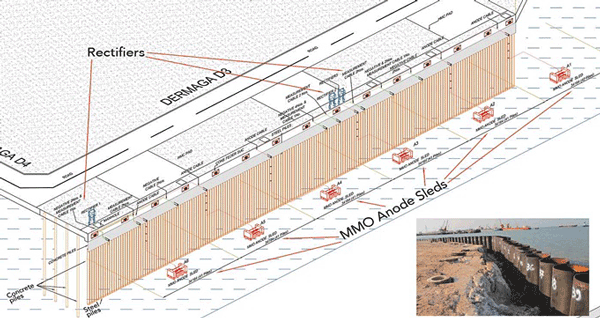
The anode sled design for this jetty project (Figure 1) consisted of six anode sleds rated for 30 years of continuous service at an output of 175 A per sled. Each sled contained two tubular anodes. Each anode, 1.52-m (60-in) long and 25.4 mm (1 in) in diameter, weighed 0.53 kg. MMO anode life is generally linear within the operating CD used in CP, so the service life of MMO anodes will decrease in proportion to the increase in current if the CP system is operated with anode output higher than their rated output. Conversely, when the operating output of the anodes is less than the rated output, their design life increases proportionally. The 175 A-rated sleds recommended for the impressed current alternative, when operating at 60% of their rated capacity once the system was polarized, would provide more than sufficient anode life, even when briefly operating at 100% of their rated capacity during the initial system polarization.
For the impressed current design, the rectifier capacity would be sized to meet the initial polarization output requirements and then be operated at a reduced level of current for maintenance once the structure was properly polarized. The actual time to fully polarize the structure would depend on several site variables, but was expected to begin in as little as one week.

After completing the conceptual design for both the galvanic anode and impressed current options, a rough budget estimate was developed based on both systems being designed for a 30-year operating life (Table 2), and presented to the owner. Based on the significantly shorter installation time and the overall cost savings associated with the impressed current option, the owner chose to proceed with the MMO anode system. Several additional factors, however, impacted the cost evaluation and the decision-making process. These included:
a) Quantity of anodes—with the galvanic CP system, over 95,000 kg of aluminum anodes would have been required. The material costs and the freight and handling efforts involved for this quantity would be significant. Conversely, the impressed current anode system only required six anode sleds—each weighing ~1,300 kg—and three rectifiers weighing 300 kg each. Total system weight of the impressed current alternative was <10% of the weight of the required galvanic anodes.
b) Installation time—for the galvanic CP system, it would require a diver to physically secure each massive anode to one of the jetty sheet piles. Assuming two anode installation crews operating in parallel with a production rate of four anodes/crew-day, the installation would take ~30 work days to install 247 anodes weighing 400 kg each. With the MMO sleds, the entire installation could be completed in less than one week using a single crew with a crane, and a single diver to help the sled settle properly on the sea floor and then route the anode cables along the sea floor and up the side of the jetty piles to the rectifier.
c) Safety—with the greatly reduced quantity of anodes required, along with the simplicity of the sled installation, the owner’s safety review determined this option would be significantly safer to install than the alternative galvanic anode system.
Installation and Commissioning
The detailed design called for installing six anode sleds at nominal locations 25 m from the sheet pile wall and spaced 34 m apart. Three oil-cooled transformer rectifiers would provide the direct current power to the anodes, with each rectifier powering a pair of anode sleds as shown in the conceptual drawing (Figure 1).

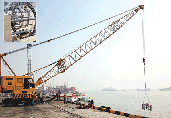
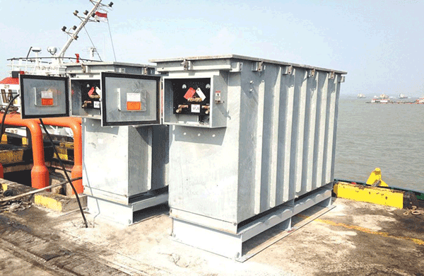
Installation of the ICCP system took less than a week to complete. Each of the sleds was installed using a land-based crane (Figure 2). The cabling was routed along the sea floor and secured in place with concrete weights installed by a diver. The cabling was routed up to the rectifiers (Figure 3) by the site electrician.

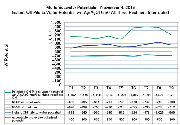
Once the system had been installed and all of the cabling was connected, secured, and inspected, the system was energized and commissioned. The first step in the commissioning process was to record native potentials along the length of the jetty to provide the baseline potentials prior to applying the CP current. All measurements were made with respect to a Ag/AgCl reference electrode using a calibrated multimeter. For potential measurements, nine test locations were identified just below the seawater surface (on the top of the submerged portion of the piles) and near the sea bed. These locations were used throughout the commissioning process.
Although the piles were coated, the overall coating condition was unknown and future deterioration was anticipated during the 30-year design life. The initial protective current requirement was considerably less than the design capacity, and that is expected to extend the life of the system. Once the system was energized, the anode outputs were measured to confirm the proper operation of each of the six anode sleds. The system was polarized within 72 h, and the total system current was reduced to ~350 A.

Instant-off potentials confirmed that the system was providing sufficient polarization to meet the appropriate design criteria per NACE SP0176-20071 and DNV-RP-B4012 for steel piles in seawater (Figure 4). The length of time from the start of the installation to the completion of the commissioning and testing was a total of two weeks.
Summary
The use of impressed current anode sleds proved to be a cost-effective alternative to galvanic anodes for this marine jetty project. The impressed current system provided a much longer anode life, greatly reduced installation time, and facilitated a safer installation process—all at a significantly reduced initial investment cost.
References
1 NACE SP0176-2007, “Corrosion Control of Submerged Areas of Permanently Installed Steel Offshore Structures Association with Petroleum Production” (Houston, TX: NACE International, 2007).
2 DNV-RP-B401, “Cathodic Protection Design” (Høvik, Norway: DNV GL, 2010).