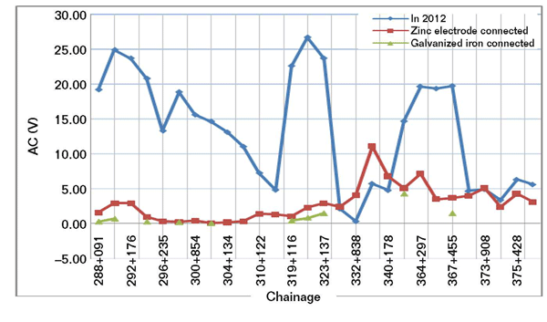
A pipeline shared a common right-of way with a high-voltage alternating current (AC) transmission line (Figure 1) and experienced high AC potentials. The practice of using deep grounds was proposed to reduce induced AC interference. The pipeline, with a three-layer polyethylene coating combined with an impressed current cathodic protection (ICCP) system, was built in 2008 in a route shared with high-voltage (400-kV) AC transmission lines. The pipeline crossed under the power lines at four locations (KP332+195, KP336+143, KP346+578, and KP366+143), shown in Figure 2.

At the crossing points, the original grounding method was installed. Direct current (DC) and AC potential surveys were then conducted over the pipeline in August 2012. Figure 2 shows that AC potentials at some locations were >15 V AC, with one as high as 27 V AC. Additional mitigation was required to accommodate personnel safety.
Geological Investigation
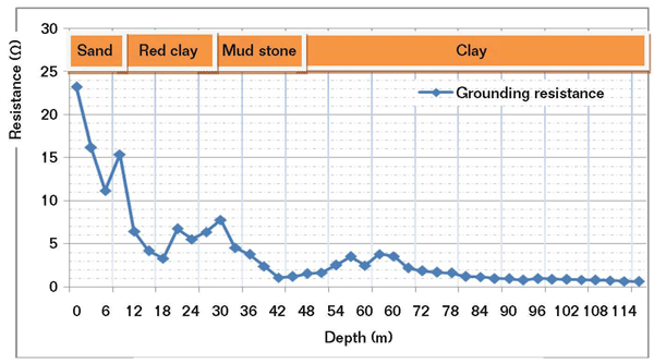
The highest AC potentials are concentrated between KP288+093 and KP367+455, which are located in a difficult mountainous area with higher resistivity at the soil’s surface. Since low earth resistance is critical to the efficient mitigation of AC interference, a deep geological investigation was carried out in September 2012. A bore hole was drilled at a horizontal distance of ~10 m from KP294+102. During drilling, the grounding resistance was recorded at depth intervals of 3 m. At the depths of 100 to 120 m, in clay-type soils, the resistance was observed to be <1  (Figure 3). It was determined that a grounding system with a depth of 120 m is feasible for mitigating AC interference.

Remediation
Based on the availability of site space, new grounding systems were located as shown in Figure 4. Polarization cells were installed close to the pipeline near the existing test posts. Zinc anodes, together with galvanized iron pipes, were lowered into a bore hole at each specific location.

A gypsum, bentonite, and sodium sulfate (Na2SO4) slurry was pumped into each hole, which enveloped the anodes and provided contact with adequate moisture. AC coupons with adjacent copper/copper sulfate (Cu/CuSO4) reference electrodes were installed close to the pipe at each site to evaluate the possibility of AC corrosion.
Resurvey
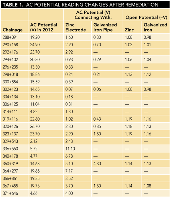
After completing installation of the new AC mitigation system and connecting the zinc electrodes and galvanized iron pipe, another AC potential survey was carried out on July 14, 2014. All AC potentials were greatly reduced and below the safety guideline of 15 V AC (Table 1). The open circuit potentials of the zinc electrodes are almost the same as the galvanized iron pipe. With the anticipated service life, the threats to the continued operation and personnel safety are greatly diminished.

Conclusions
Proper design and installation of a grounding system are key to draining AC interference. Since polarization cells have the ability to drain AC and block DC, their performance must be monitored periodically by testing the DC potential of the buried pipeline to confirm that CP remains effective. In addition, the reliable life of grounding with zinc electrodes and galvanized iron pipe also should be considered for extending service life.
Bibliography
DEP 30.10.73.33. “Installation and Commissioning of Cathodic Protection Systems.” The Hague, The Netherlands: Shell Global Solutions.
NACE Publication 35110. “AC Corrosion State-of-the- Art: Corrosion Rate, Mechanism, and Mitigation Requirements.” Houston, TX: NACE International, 2010.
NACE Standard SP0177-2014. “Mitigation of Alternating Current and Lightning Effects on Metallic Structures and Corrosion Control Systems.” Houston, TX: NACE International, 2014.
ABOUT THE AUTHORS
LI HONGQI is a senior corrosion engineer at China Petroleum Pipeline Inspection Co., Ltd., No. 166 Aimin East Rd., Langfang City, China, e-mail: lhq-163@163.com. He conducts external corrosion direct assessment surveys for buried pipelines, inspection, and assessment for aboveground tanks. He has a B.S. degree in corrosion and protection from Beijing Chemical University and is a nine-year member of NACE International.
DONG YINGJUN is a pipeline engineer at China Petroleum Pipeline Bureau Middle East, 309, Bldg. 1, Emaar Business Park, the Greens, PO Box 27311, Dubai, UAE, e-mail: oliverdong2008@gmail.com. He has an M.S. degree from the Beijing University of Aeronautics and Astronautics (2007). Prior to joining the company he worked as an oilfield technical engineer and pipeline engineer.
ZHAO XIAOMIN is an engineer at the China Petroleum Pipeline Co. Technical Service Center, No. 18 Sihai Rd., Development District, Langfang City, 065000, China. She has 20 years of experience in testing and maintenance of oilfield facilities. She has a B.S. degree in oil and gas storage from China Petroleum University (2008).