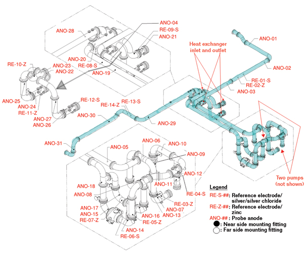
At a power plant in Asia, a total of 120 m of above-grade auxiliary cooling water (ACW) pipe was constructed to convey seawater from ACW pumps to a plate-type heat exchanger. The ACW pipe was a 16-in (406-mm) diameter carbon steel (CS) pipe lined with 8 to 12 mils (0.2 to 0.3 mm) of coal tar epoxy. The pipe spools were joined by flanges. Figure 1 shows the general arrangement of the ACW pipe.
Failure Analysis
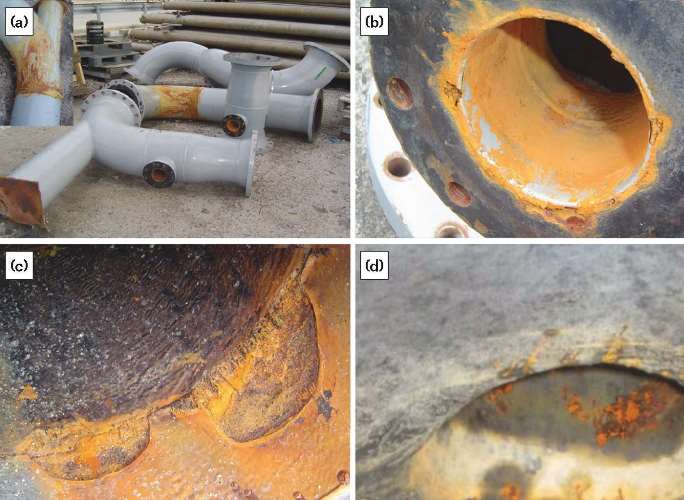
After six months of operation, leaks appeared at welds on lower portions of the pipes. Subsequently, more leaks were found at welds and flanges. After taking apart the pipe spools, it was found that all leaks developed at pipe welds and between the flanges. Less significant corrosion was also observed on areas away from welds and flanges. Figure 2(a) shows some of the pipe spools that were replaced.
Corrosion at Flanges
When two flanges are joined together in seawater service, crevice corrosion may initiate at any gap between the flanges. The entire ACW piping system had dozens of flanges that were possible sites for crevice corrosion attack. Without a cathodic protection (CP) system for corrosion protection, crevice corrosion could be severe, as shown in Figure 2(b).
Pipe Body Corrosion
Without CP, corrosion developed at coating defects and then crept underneath the coating. Flowing seawater chipped off damaged coating, causing more bare steel areas to be exposed. Figures 2(c) and (d) show the coating failure and corrosion on the pipe body. Unlike crevice corrosion at flanges and welds, this corrosion was localized and would take more time to penetrate the wall.
Corrosion at Welds
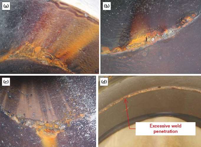
The most severe corrosion attack occurred at the welds and was caused by crevice corrosion. Due to incomplete weld penetration at some joints, there were gaps at the welds inside the pipe. Moreover, sandblasting during surface preparation was unable to thoroughly clean those gaps and the coating quality was compromised as a consequence. Because of the poor coating quality at the welds and the absence of a CP system in seawater service, crevice corrosion attack at the welds initiated and accelerated.
Corrosion also occurred at welds with excessive weld penetration, but this was relatively minor compared to corrosion of the welds with incomplete weld penetration. In time, however, more corrosion would be expected at or near the welds with excessive penetration caused by the compromised surface preparation. The coating specification called for grinding the welds to NACE SP0178,1 Designation C, Appendix C. Unfortunately, this requirement had not been fulfilled. The corrosion morphology at welds with incomplete penetration is shown in Figures 3(a) through (c), and excessive penetration is shown in Figure 3(d).
ACW Piping Corrosion Protection Retrofit
It was concluded that CP in conjunction with coating repair would provide adequate corrosion protection. All ACW pipes were above grade, so it was not practical to electrically isolate the ACW pipe, since pipe supports, grounding systems, and other metallic structures contacting the pipe would have made the isolating flanges ineffective.
The retrofitting measures were carried out as follows:
• The ACW pipes were completely disassembled.
• The pipe interiors were inspected for corrosion and internal coating damage.
• The damaged lining was repaired and spools with severe corrosion were replaced.
• An impressed current CP (ICCP) system was installed.
Cathodic Protection Design
Cathodic Protection Design Parameters
The ICCP system was designed using the following parameters:
• CP criterion: 100 mV of cathodic polarization, per NACE SP0169,2 compared to the measured baseline potential
• Seawater resistivity: ρ = 25  -cm
-cm
• Circulating water velocity: V = 3 m/s
• Coating efficiency (at the end of CP design life): 85%
• Current density: 100 mA/m2 for 100 mV polarization3
• Anode type: mixed metal oxide (MMO) probe-type anode with an outside diameter of 3 in (19 mm)
• Anode length: active length = 3 in (19 mm); inactive length = 4 in (102 mm); total length = 7 in (178 mm)
• Anode design life: 25 years
• Total area of pipe interior: 150 m2
• Estimated area of bare metal that receives CP current: 17 m2 (two circulating water pumps: 2 × 2 m2; one strainer: 1 × 1 m2; and one plate-type heat exchanger with two inlets and two outlets:4 4 × 3 m2)
• Calculated maximum probe anode length allowed:5 12 in (305 mm) (>7 in)
• Minimum anode spacing based on potential attenuation: 8 m
• Minimal current requirement: 4 A
• Calculated minimum number of anodes: 17
Cathodic Protection Components Summary
Based on the calculations, the following ICCP components were required to provide the ACW pipe retrofit with corrosion protection:
• One automatic rectifier with direct current (DC) output ratings of 12 V and 25 A
• One anode junction box with variable resistors
• Thirty-one probe-type MMO anodes
• Seven probe-type zinc reference electrodes
• Seven probe-type silver/silver chloride (Ag/AgCl) reference electrodes
• Cabling
Installation
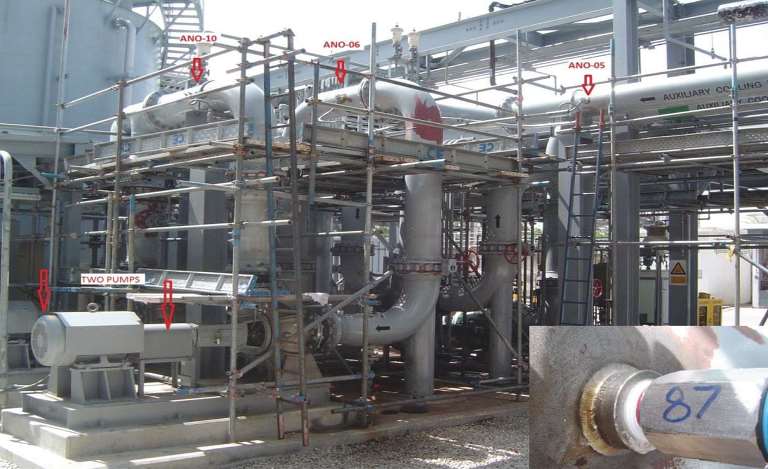
Figure 1 shows the locations of the anodes and the reference electrodes along the ACW pipe. All probe-type anodes and reference electrodes came with a factory-sealed lead wire. Figure 4 shows part of the auxiliary cooling system while the ICCP system was under construction. Here, 11-in (32-mm) NTP 3000# 316L stainless steel (UNS S31603) half-couplings have been welded on the pipe. The anodes and reference electrodes were threaded into the pipe through the half-couplings. A total of 31 probe anodes were installed. Anode lead wires were routed to the anode junction box, and reference electrode lead wires were routed to the rectifier. Hot-dip galvanized steel conduits were used to accommodate the lead wires.
Cathodic Protection Commissioning
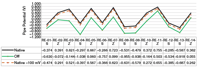
Due to the pipe configuration, air pockets might have developed in the pipes, and anodes in air pockets would not have current output. If a single anode failed to discharge current, the system was designed so that the adjacent anodes on each side would still be able to provide CP to the pipe. A total of 14 reference electrodes provided pipe potential monitoring. The protection criterion for the CP retrofit system was a minimum of 100 mV of cathodic polarization compared to the measured native (baseline) potential. This was measured as the difference between the measured native potential and instant “off” potential of the pipe. Prior to measuring the pipe native potential with respect to each reference electrode, the ACW pump was operated for a minimum of two hours. The rectifier was then energized and the current output was gradually increased to achieve polarization. The rectifier was allowed to operate continually for 24 h to stabilize the polarization before further adjustment. Each anode’s working status was checked to ensure that all anodes had been installed properly. After 24 h, the CP system was readjusted to meet the CP criterion. The final DC output of the rectifier was 0.35 V and 6.4 A. All test results, listed in Figure 5, show that a minimum of 100 mV of polarization had been achieved at each test location.
Discussion
Cathodic Protection
When the lining was the only means of protecting the pipe interior against corrosion, internal corrosion attack caused the pipe to leak after six months. Since the added CP was first put into operation, leaks have not developed in the ACW pipe in three years. After repair, the internal pipe coating was expected to be in good shape. Since isolating flanges were not installed on the ACW pipe, most of the DC from the rectifier went to the bare metal areas of the heat exchanger, the ACW pumps, and the strainer. The test results show that the instant “off ” potential shifts for the ACW pipe range from –249 to –765 mV. These shifts have significantly reduced the corrosion rate of the ACW pipe.6
Lining
Surface preparation is critical to coating performance, especially in seawater exposure. Coating specifications shall be strictly followed; QA/QC procedures shall be clearly addressed in the contract and strictly implemented at all stages in the processes.
Conclusions
• Coating alone cannot provide sufficient protection against corrosion in seawater applications.
• A coating in conjunction with CP should be utilized to effectively mitigate seawater corrosion.
• A minimum DFT of 20 mils is recommended for a pipe lining system used in seawater service.
• For immersion service, as a minimum, surface preparation of welds should meet NACE SP0178, Designation C, Appendix C.
• Welds with incomplete penetration are not acceptable.
References
1 NACE SP0178-2007, “Design, Fabrication, and Surface Finish Practices for Tanks and Vessels to Be Lined for Immersion Service” (Houston, TX: NACE International, 2007).
2 NACE SP0169-2013, “Control of External Corrosion on Underground or Submerged Metallic Piping Systems” (Houston, TX: NACE, 2013).
3 Metals Handbook, 9th ed., Vol. 1 (Materials Park, OH: ASM, 1978).
4 J. Morgan, Cathodic Protection, 2nd ed. (Houston, TX: NACE, 1987).
5 NACE CP4 Manual (Houston, TX: NACE, 2004).
6 “One Hundred Millivolt (mV) Cathodic Protection Criterion,” NACE, 35018, 2008.