In April 2013, the Las Vegas Valley Water District attempted to install a 500-ft (152-m) deep anode bed for an impressed current cathodic protection system. This depth was required to minimize stray current effects on nearby utilities. Before the anodes could be installed, ground water began flowing out of the top of the hole at ~50 gal/min (189 L/m). This article describes the problems encountered and the solutions developed.
During attempts to install a deep anode bed to a depth of 500 ft (152 m) for an impressed current cathodic protection (ICCP) system, groundwater flowed out of the drilled hole. After consulting the driller and Las Vegas Valley Water District (LVVWD) hydrologists, it was determined that a flowing artesian aquifer had been encountered at a depth of ~412 ft (126 m). Concrete was poured down the hole, filling it to a depth of 350 ft (107 m) and sealing the aquifer. The hole was then redrilled to 400 ft (122 m), and the anode bed was installed. In addition to preventing the required anode bed depth (500 ft) to be attained, this process added time and expense to the project. Approximately one month after the installation of the anode bed, water was penetrating the anode cable, migrating between the conductors and insulation, and traveling up the cables into the rectifier. Figure 1 shows calcium carbonate (CaCO3) deposits at the anode
cable connectors that resulted from the artesian aquifer pressure and wicking action inside the cables.
This artesian aquifer is formed by water percolating into the ground in the mountains on the west side of the Las Vegas Valley. The aquifer is bound by an impervious layer on top and fault lines that offset the aquifer’s depth. The faults form barriers to the natural flow of groundwater from west to east across the valley and can increase artesian heads on the west side of the faults. There are also shallow aquifers above the artesian aquifer. Figure 2 shows a map of the area with fault lines and the location of the anode bed as originally designed and as repositioned.
The original anode bed was at an elevation of ~1,920 ft (585 m) and 2,050 linear ft (625 m) west of the fault. A new anode bed was required at an elevation of 1,840 ft (561 m) and 300 linear ft (91 m) west of the fault line. It was predicted that artesian water flow would likely occur at a more shallow depth at the new anode bed location, and a method of installing an anode bed subject to these conditions was investigated. There are three main issues with installing a typical anode bed in a flowing artesian aquifer:
-
Water flow would carry the coke breeze out the top of the hole before it could settle and pack around the anodes.
- Multiple aquifers would need to be sealed to prevent contamination of the clean aquifers from surface waters.
- Water flow from the anode bed after completion would need to be controlled.
Researching the situation revealed three potential solutions. One solution was to install the anode bed above the artesian aquifer. This was not acceptable because it would create a significantly higher chance of stray current interference with other utilities. The second solution was to install the anodes without coke breeze, because the aquifer would cause very low resistance in the adjacent soil. This, however, could lead to contamination of the aquifer. The third solution was to drill the hole, fill it with concrete through the artesian layer, and redrill through the concrete. This would likely have to be performed multiple times to successfully stop the water flow. Needless to say, this would drastically increase the cost and time of the project. Other options were evaluated, including the installation of a steel casing to seal the active water column. This also would have significantly increased the cost of the anode bed. Therefore, a new method of installing a deep anode bed in a flowing artesian aquifer was required.
It was necessary to utilize a low-resistance anode backfill material that would remain in place while countering the force of the flowing artesian water, as well as prevent contamination of the aquifer. A coke breeze-impregnated grout material was chosen as the best material for this situation.
Anode Bed Design
To address the challenge of loading a CP bore with materials that could stop artesian pressures and flows, a new patented CP system was selected that uses a solid-forming backfill consisting of a concrete and carbon matrix, and specially prepared anodes. The backfill material is basically a conductive grout as well as a sealant. Since the aquifer contains potable-quality water, it was essential that this backfill material not only seal the aquifer and stop the water flow, but also seal all of the multiple aquifer zones to eliminate cross-contamination pathways.

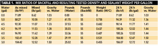
After studying the aquifer’s pressure and flow, it was determined that the aquifer pressures could be overcome and sealed when the backfill material was mixed to a particular density. Additionally, the backfill could encapsulate the anodes. Table 1 shows the specific mix ratios of the packaged backfill and water, and the resulting densities and sealant rating weights per gallon. The ratio of 3.8 gal (14.4 L) of water per 55-lb (25-kg) bag of backfill was selected to address the specific issues at the selected site for the new anode bed. Since this ratio resulted in a specific gravity of 1.44 and a sealant weight of 11.9 lb/gal (1.4 kg/L), along with the rapid cure rate of the material for initial set, it was determined the design would be successful against the anticipated pressures and flows.
 Essentially, the design was to place the bore base at a depth of 500 ft, with anodes spaced in the bore up to the top of the active zone at 300 ft. Each individual anode wire was to be collected at the surface and run inside a conduit to the shunt box for connection. A vent pipe was not used in this design as it was not necessary for the material in this CP system and could compromise the sealed bed matrix. Each of the anodes used is a specially covered mixed-metal oxide that is rated up to 5 A output.
It was essential that the installing company carefully mix the backfill and pump it into the well bore from the bottom up using a “tremie” pipe in a continuous pumping operation. The mixer, a grout pump, was used to easily attain precise control. The installing company had previously used this equipment in concrete seal pump work; therefore, adapting it to this backfill was a simple process.
Installation
Construction of the anode bed began on August 5, 2014. The mud drilling rig was
set up over the bore site, and drilling proceeded to a depth of 510 ft (155 m). The artesian water flow came up to the top of the bore hole and into the holding tank. Mud tests showed the specific gravity of the mud had fallen to 1.06 and a density of 8.5 lb/gal (1.02 kg/L). Since loading the hole was expected to occur the next day, sand was mixed into the mud in the bore in an attempt to stop the overnight flow of artesian water. Preparations were also made to capture the silt and divert the water into a storm drain in the event of an overflow, but they had limited success. By morning, the tank had overflowed with artesian water, mud, and sand, and the flow was calculated to be ~15 gal/min (57 L/m).
The bore was prepared for filling with anodes and backfill by first removing the drill pipe, then inserting the rigid tremie pipe to the bottom of the bore. Anodes were loaded one by one into the bore—the drop to their specified locations was hand-controlled since they were descending against the flowing artesian water and mud. Each anode reached its specified depth without incident, and mixing operations with the grout pump assembly were started. Careful measurements of the mix density were taken by mud cup and mud balance tests to achieve and maintain the appropriate density of 11.9 lb/gal for the backfill. Pumping began and the backfill mixture started to displace the water and mud above the level of the tremie pipe, then push upward and around the anodes. Once an approximate backfill depth of 350 ft was achieved, all artesian water flow stopped. Pumping continued until the top of the active zone (~300 ft below grade) was reached (Figure 3). Once the pumping was completed, the
tremie pipe was removed and entrained backfill slipped into the bore as the pipe was extracted. The result was a completely sealed active zone with nothing but backfill and anodes.
 Completion Steps
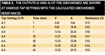
Once the active zone had been filled, the mixture was allowed to set overnight in preparation for the top sealant to be pumped into the bore. There was no artesian water flow overnight, so the top sealant material was placed. The anode wires were then installed in conduit below ground to the shunt box for connections to the anode bus and rectifier. The system was allowed to cure for 30 days to ensure the backfill was completely set and all the aquifers were sealed.Once the cure period had ended, direct current was applied to the anodes to ensure performance was achieved. Table 2 lists output values of each anode in the solid backfill.
Conclusions
The CP system with the solid-forming backfill can be designed for, and practically installed in, flowing artesian aquifer zones. The technology allows the protection of all subsurface aquifers from cross-contamination by a sealant value of 3.7 × 10⁻⁷ cm/s, which is comparable to bentonite seals. This special backfill is NSF 60 certified to ensure water quality is maintained to the highest standards. Installation is easy to perform with common equipment typically used for traditional deep groundbeds, and the backfill material prevents the flow of artesian water to the surface and the loss of groundbed due to artesian flows.