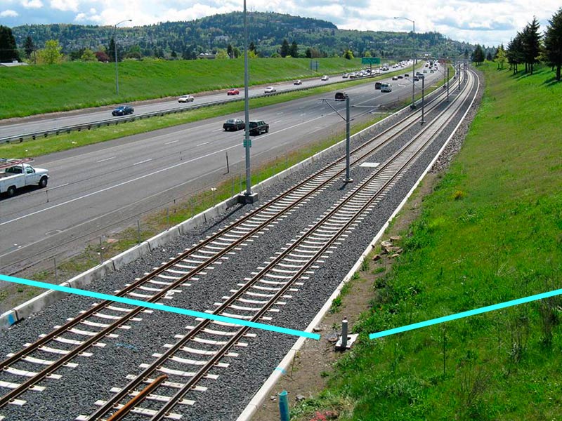
When a light-rail line was constructed parallel to an existing interstate highway near Portland Oregon, it crossed five pressurized, large-diameter (60-in [1,524-mm]) steel water transmission pipelines that carry drinking water into the city from nearby reservoirs. The transit corridor was considered a high-consequence area because a pipe failure could disrupt both light-rail and highway traffic. To protect the pipes in the transit corridor where they crossed underneath the light-rail tracks, construction of the line included retrofitting the pipelines with a precast concrete box culvert casing and installing an impressed current cathodic protection (ICCP) system.
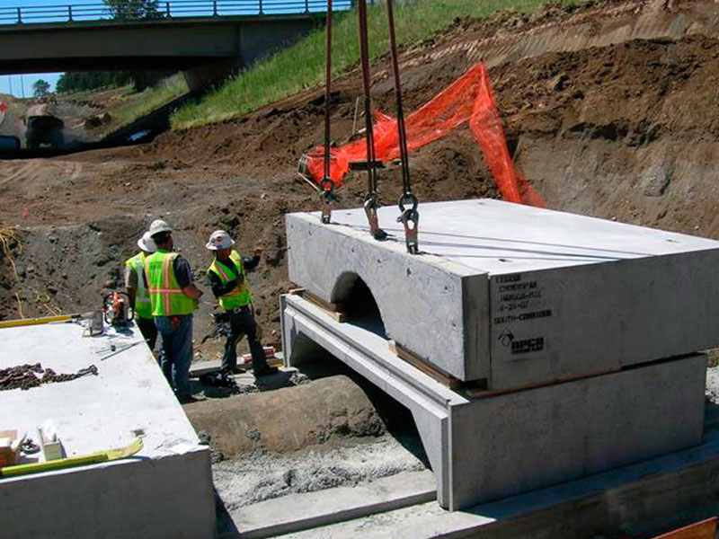
According to NACE International member Stuart Greenberger, senior engineer with the Portland Water Bureau, the main reasons for installing the box culvert casings were to protect the pipes from the increased soil load resulting from grade changes made to accommodate the train tracks, facilitate pipe operation and maintenance without disturbing the tracks, and electrically distance the pipes from close coupling with the light-rail system. “The new threat [to the water pipelines] was stray current corrosion from the light rail,” he says. Typically, cased pipelines comprise a carrier pipe inserted into a larger diameter casing pipe. In this particular instance, Greenberger explains, the five carrier pipelines would need to be drained and have segments removed for a casing pipe to be installed. “It would be an extensive job to get the water out of these pipes, and we didn’t want to take the conduit out of service,” he adds. A practical and economical solution was to build a box culvert around the ~80-ft (24-m) portion of each pipeline that crossed under the light rail while the pipes remained in service. The box culvert was determined to be less costly than constructing a split casing around the intact pipe.
 Four of the pipelines, when originally installed, were made of steel with a dielectric coating. The fifth one was bar-wrapped steel cylinder concrete pressure pipe, which is comprised of a welded steel cylinder with steel reinforcing bars wrapped around the cylinder to provide strength. Corrosion protection for the steel components of the concrete cylinder pipe is provided by an internal concrete lining and external mortar coating. When the highway was built, the portions of coated steel pipe that crossed under it were replaced with bar-wrapped steel cylinder concrete pressure pipe with poured concrete along the sides. Three of the coated steel pipelines were subsequently fitted with ICCP systems at areas along the route that were considered to be particularly corrosive.
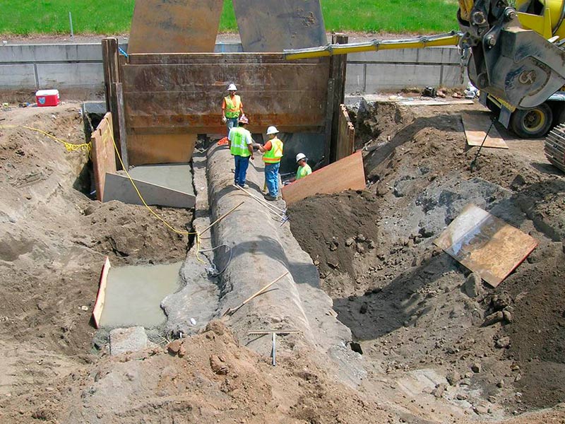
To install the box culverts, small portions of each pipe were excavated at 10-ft (3-m) spans, and concrete support saddles were cast in place around these portions of the pipe while the remaining pipe was left in its existing bedding. Once the support saddles were completed, the pipe between the saddles was excavated. This technique provided a means to create support for the pipe while it was still in service, Greenberger notes. After the pipe was completely excavated, the previously installed concrete around the haunches of the pipe was removed, and a new, continuous concrete foundation footing and floor slab were poured underneath and up the sides of the pipe. Hot-dip galvanized steel pipe saddles with a dielectric coating, designed to hold the pipe in place if the groundwater level should ever rise above the pipe and make it buoyant, were placed over the pipe and fastened to the floor slab with grout-covered bolts. The box culvert and end walls were then put into place and covered with a minimum of 5 ft (1.5 m) of backfill.
 For each of the five water transmission pipelines, which are spaced ~1 mile (1.6 km) apart along the transit corridor, a separate ICCP system was installed. Each CP system has the same design, which includes an automatically controlled rectifier and a permanent copper/copper-sulfate (Cu/CuSO4) reference electrode (CSE) for rectifier control that is positioned near the pipeline where it crosses under the light-rail tracks. The rectifier uses the CSE to determine the structure-to-electrolyte potential and then continuously adjusts its output to maintain a pre-set potential for the structure. A CP coupon drop tube test station, installed a few feet away from the CSE (and also near the point where the pipeline and light-rail tracks cross), provides a potential reading that represents the pipe-to-soil (P/S) potential. A 200-ft (61-m) deep continuous column anode bed, built 100 ft (30 m) below grade, contains 10 cast iron anodes in coke breeze. Each anode bed was buried 75 ft (23 m) away from the pipeline and test station, Greenberger says, so electrical current from the anode bed would protect all portions of the pipe crossing underneath the transit corridor.
Normal operation of each ICCP system requires ~1.0 A of rectifier output to maintain pipe potentials of –1.0 V, the “on” potential as measured at the CP coupon drop tube test station when the rectifier is operating and generating current. A nearly constant pipe potential indicates a well-insulated rail system with high track-to-earth resistance. Greenberger notes that rectifier output readings and potential readings indicated normal operation for four of the ICCP systems.
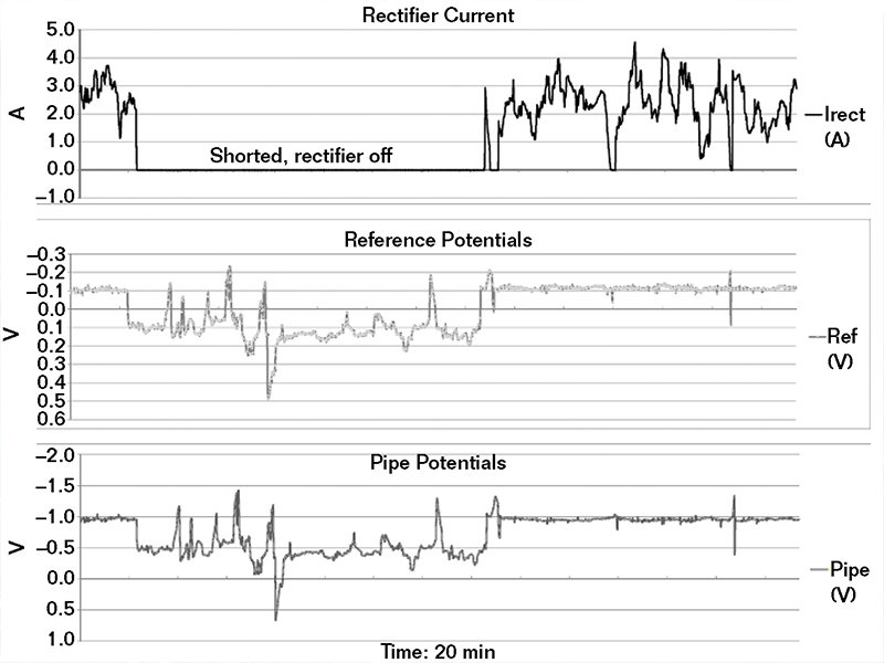
At one crossing, however, the ICCP system was experiencing a problem. When the rectifier was turned on, the current output required to maintain fairly constant pipe potentials varied between 0.0 and 4.0 A. When the rectifier was turned off, the P/S potentials varied from –1.0 to +2.0 V. The potential measurements displayed the characteristic signature of train movement, Greenberger explains, which meant the pipe was being subjected to stray current driven by the track voltage. The varying output from the rectifier indicated a track-to-earth short.
 When the light-rail line was constructed, a track switch at a transit station was located directly over the pipe at this particular crossing. To ensure the track switch didn’t freeze, a heater was installed on it and electrically grounded above the pipe. The grounding created a 25-? track-to-earth short and allowed current from the track to enter the ground just above the pipe. “The whole idea is to isolate the rail from the ground because that’s where stray current comes from, and we don’t want current exchange between the rail and the pipe,” Greenberger says. “Instead, when they grounded the heater at that location, the rail was no longer isolated. As current was coming off the rail, the rectifier was putting current in the ground to offset the rail current. The amperage from the rectifier varied significantly because it was countering the stray current from the rail,” he adds. The rectifier was doing exactly what it was supposed to do, and doing an exceptional job, he notes, commenting that the rectifier was able to keep pace with the stray current signature of the train and hold the pipe potentials relatively constant—within 100 mV.
The stray current, measured by placing a shunt in the track switch heater’s electrical ground circuit, ranged from 0.0 to 300 mA. Greenberger comments that the close proximity of the short to the rectifier’s control reference electrode, coupled with the somewhat remote deep anode bed trying to offset the effect of the local current, caused a relatively small voltage gradient from the stray current to drive a large amount of current output from the rectifier, which can use up the anodes at a faster rate. In this case, he adds, the stray current problem was resolved by installing a polarization cell replacement (PCR) on the grounding for the track switch heater. The PCR blocks direct current (DC) but allows alternating current (AC) grounding, so the track switch heater is AC grounded and the DC stray current is blocked. This allowed the ICCP system to function properly.
 To avoid a large current output from an automatically controlled rectifier to counterbalance a small amount of stray current at a closely coupled pipe-to-track crossing, Greenberger suggests operating automatic rectifiers in a current limiting mode, as well as monitoring the system. When a small-magnitude stray current causes a large rectifier output, overvoltage concerns such as coating disbondment can potentially limit the benefits of the automatically controlled CP system. Instead of remote deep anode beds, he says, one alternative is to use distributed anodes close to the crossing to lessen the rectifier current required to offset the stray current. For example, during the construction of box culverts for similar projects, canister anodes were installed for the CP system. Since an automatically controlled pipeline CP system might trace a voltage gradient in the soil, Greenberger suggests making the control reference electrode integral with a CP coupon test station, including a drop tube, where possible.
More information on this case study can be found in CORROSION 2014 paper no. 4008, “Corrosion Control System Performance for Large Diameter Water Mains in a Light-Rail and Interstate Highway Corridor,” by S. Greenberger and G. Wallis.Contact Stuart Greenberger, Portland Water Bureau—e-mail: Stu.Greenberger@portlandoregon.gov.