Steam condensate corrosion can be encountered in many industries (e.g., power generation, chemicals, pulp and paper, food and beverage) and in building heating systems. Corrosion can occur in steam-users (e.g., heat exchangers and reactors), in steam supply lines (usually at distant, cooler locations), and in condensate return lines.
When the non-condensable gases oxygen and carbon dioxide (CO2) are present in the system alone, or in combination, they can make the hot condensate very corrosive. These gases enter the steam-condensate system through several means: (i) along with boiler feedwater as “free” or entrained gases; (ii) when condensing steam creates a vacuum and air is drawn in; or (iii) in the case of CO2, as a result of the thermal breakdown of carbonates and bicarbonates in the feedwater.
Other corrosive gases may be present in the steam-condensate system, including ammonia (NH3), hydrogen sulfide (H2S), and sulfur dioxide (SO2).
CO2 dissolves in the aqueous condensate to form carbonic acid.
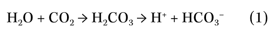
Hence, the condensate will contain hydrogen ions (H+) that can promote corrosion via the following mechanism (M = metal):
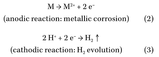
The presence of oxygen in the condensate can enable the following additional cathodic reactions, which can greatly stimulate corrosion attack:
Corrosion Damage
The type of corrosion damage encountered depends on the material of construction, the non-condensable gases present, and the way in which the steam condensate collects and flows.
For carbon steel (CS) equipment, the presence of oxygen in the condensate usually creates pits that are often filled with corrosion products (Figure 1). The presence of CO2 creates mesa-type attack or deep grooving (Figure 2). Corrosion products are often carried away with the flowing condensate and may be deposited at other locations in the system where flow rates are lower, or the pressure is reduced.
 grooving.")
Cupro-nickel heat exchanger tubes can experience exfoliation attack (“leafing”) where thin layers of the tube metal are converted into oxides.1 Oxygen is primarily responsible for this type of attack, but other gases, such as CO2 and ammonia, help to determine the extent and morphology of the corrosion damage.
The slight tilt routinely given to the horizontal tubes in heat exchangers (with steam on the shell-side) can promote condensate flow toward one side of a baffle or tube support plate. This localized flow can create deep grooves in the tubes immediately adjacent to the baffle or support plate.2 Brass tubes are especially susceptible to this form of attack.
Condensate is ejected at high velocities from some steam traps and erosion-corrosion can occur on the internal walls of the discharge piping. In steam service, magnetite scale (Fe3O4) often forms on steel surfaces. Small particles of this scale can become detached—particularly in equipment that is used intermittently or cyclically. When ejected from steam traps, these particles add to the erosive effect of the condensate. Erosion-corrosion can also occur when constantly rising and falling condensate levels act to scour away protective oxide or inhibitor films.
Cavitation-type failures have occurred where cold water has been injected into condensate lines in order to cool the condensate.1 Violent steam collapse can cause severe metal loss around the injection points and immediately downstream.
Leakage of a process stream into the steam-side of a vessel can result in a highly corrosive condensate, as with leaking heat exchanger tubes. In such cases, it may be necessary to direct that condensate stream to a drain rather than to return it to the boiler.
Corrosion Control
Boiler Feedwater Pretreatment
Feedwater pretreatment is the principal defense against steam condensate corrosion and great care is taken to remove O2, CO2, carbonates, and bicarbonates from boiler feedwater. Mechanical and chemical deaeration are well established and a detailed description of them is beyond the scope of this article.
While most of the oxygen is physically removed during deaeration, the last traces can be captured by chemical additives called “oxygen scavengers.” (See “Oxygen Scavengers” section.)
Volatile Corrosion Inhibitors
Despite the pretreatment of boiler feedwater, some CO2 or oxygen may still enter the steam supply. In recent years, significant advances have been made in the formulation and application of volatile corrosion inhibitors that are transported through the steam supply lines and then act to mitigate corrosion in the condensate system.3-5 These inhibitors are (i) filmformers, which coat metal surfaces with a protective film, and (ii) neutralizers, which act to neutralize carbonic acid. Decomposition of the inhibitors can produce ammonia. Since ammonia forms an alkaline solution upon dissolving into condensate, it can be beneficial in neutralizing carbonic acid. However, ammonia may lead to corrosion and stress corrosion cracking (SCC) of copper-based materials.
Corrosion inhibitors, particularly film-formers, can have a detergent effect upon metal surfaces. Deposits and corrosion products can be carried away by the flowing condensate and can accumulate in other parts of the system.
Oxygen Scavengers
Sodium sulfite and hydrazine are well established oxygen scavengers. They react with oxygen as shown below:
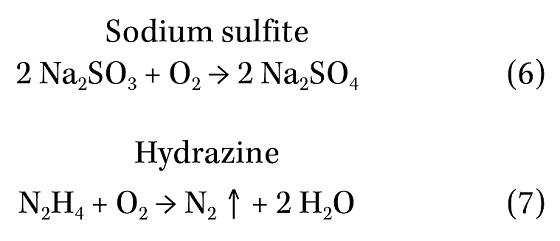
Hydrazine reacts with hematite (Fe2O3) on steel surfaces to form a more protective film of Fe3O4. Because of safety concerns, hydrazine has been largely superseded by carbohydrazide (CH6N4O), which is also claimed to help “passivate” metal surfaces. Diethylhydroxylamine (C4H11NO) is another oxygen scavenger that is claimed to help passivate steel and copper surfaces.
More information on oxygen scavengers can be found in the literature.3-4 In some processing plants, clean condensate is collected and used for product mixing, dilution, or washing; hence, it may be inadvisable to use inhibitors or scavengers for fear of contaminating the product(s).
Materials Selection
Plain CS is susceptible to steam condensate corrosion—either in the presence of CO2 or oxygen (see Figures 1 and 2). However, it may represent the most economical choice provided regular inspection and timely replacement of corroded equipment can be performed.
More corrosion-resistant materials include chromium-molybdenum steels, chromium steels, stainless steels (SS), NiCr-Fe alloys, titanium, and some copper alloys.2,6 Chromium-containing steels have been reported to have good resistance to erosion-corrosion.7 CS piping, which was internally clad with SS, has been used for lines carrying very aggressive condensate.8
metal and aluminum bronze have been reported to provide resistance to steam condensate when used as tubesheets in heat exchangers.2 As previously mentioned, the use of corrosion inhibitors or oxygen scavengers usually results in the presence of amines and/or ammonia, which can adversely affect copper alloys.
The presence of small amounts of chloride in the steam-condensate system could create problems for common austenitic SSs because they are susceptible to chloride pitting and SCC. Raw water dripping onto the outer surface of a hot condensate pipe made of austenitic SS could also cause SCC.
In order to avoid galvanic corrosion, care should be taken to ensure that dissimilar metals are not combined in the internal components of pumps and valves. Materials selected for steam-condensate service should conform to the ASME code and/or other applicable codes.
Venting
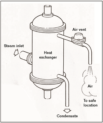
 grooving.") Air can become trapped in steam lines and steam-users during startup. Vents can be installed to release air, thus allowing the steam to fill the piping and equipment more completely (Figure 3). These air vents can be operated manually or automatically. Automatic vents sense the difference between air and steam and stay open to allow most of the air to escape.9
Air can become trapped in steam lines and steam-users during startup. Vents can be installed to release air, thus allowing the steam to fill the piping and equipment more completely (Figure 3). These air vents can be operated manually or automatically. Automatic vents sense the difference between air and steam and stay open to allow most of the air to escape.9
Oxygen and CO2 swept along in the steam supply can collect in localized “pockets” within steam-users. It is sometimes possible to install a special venting system to allow these gases to escape. For example, through a suitable fitting and an access port in the shell of the vessel (e.g., a blind flange), it may be possible to insert a small-diameter SS tube so that the interior end of the tube reaches into the gas “pocket.” The external end of the tube can be fitted with a small SS valve. After startup, the valve can be gradually opened to allow non-condensable gases to escape from the vessel.
Air Ingress
When the steam supply is turned off, the steam will start to condense and a vacuum can develop. If the vessel or steam header is fitted with a vacuum-breaker, it will open to admit air. The in-leakage of air, consisting of 21 vol% O2 and 0.04 vol% CO2, will contribute oxygen and a smaller amount of CO2. Air can also be drawn into systems through small leaks at gaskets, valve stem packing, and pump glands—and through any air vents that might still be open.
Steam Traps
Steam traps open to allow condensate to escape from steam-users or steam headers and they close to prevent steam from escaping. Several types of steam trap are available including, but not limited to, float traps, bucket traps, thermodynamic traps, thermostatic traps, and liquid expansion traps. In addition to effectively ejecting corrosive condensate, steam traps can also allow non-condensable gases to escape. Some trap designs (e.g., thermostatic) are better than others in this regard. A detailed discussion of steam trap design and operation, correct sizing and positioning, and associated piping is beyond the scope of this article. Helpful literature is available on steam traps.10
Equipment Design
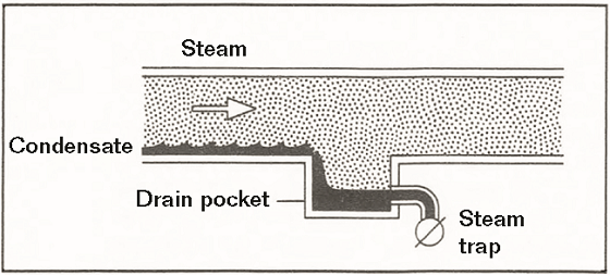
In general, it is usually easier and less expensive to replace piping than it is to replace steam-users, such as heat exchangers and pressure vessels. To control corrosion, it is essential to minimize the residence time of condensate in a steam-user by efficiently collecting it (Figure 4), ejecting it, and piping it back to the boiler.
Condensate piping systems that provide gravity drainage are ideal. Care should be taken to avoid locations where the corrosive condensate can collect, such as low spots and dead-legs. Moderate flow rates help to minimize the possibility of erosion-corrosion. Threaded pipe joints are particularly susceptible to corrosion because of the reduction of wall thickness, due to the thread cuts, and the presence of residual stresses. Hence, whenever possible, buttwelded joints are preferred. Information is available on the design of efficient condensate piping systems.10
 To mitigate erosion-corrosion damage, some plants have installed heavy-walled piping and fittings to provide a greater corrosion allowance. Long-radius elbows have also been installed to streamline condensate flow and reduce impingement.
When designing a steam-user, the positions of the steam inlet, condensate drain, and air vent need to be carefully considered. As the steam first enters the vessel, a sweeping flow can help drive trapped air toward the air vent and facilitate condensate movement toward the steam trap (Figure 5).9
In horizontal shell-and-tube heat exchangers with steam on the shell side, condensate will run off the tubes and collect along the bottom of the shell. Tube support plates that rest on the inner surface of the shell can inhibit condensate flow toward the outlet nozzle. To facilitate efficient condensate removal, notches should be cut out of the bottoms of the tube supports (Figure 6).11
Conclusions
Diligent boiler feedwater treatment, involving mechanical deaeration and chemical treatment, is the primary defense against steam condensate corrosion.
Volatile corrosion inhibitors, carried through the steam supply lines, help to control condensate corrosion. Film-forming inhibitors coat metal surfaces with a protective film and neutralizing inhibitors act to neutralize carbonic acid. Scavengers act to “mop up” the remaining traces of oxygen in the system.

Attention should also be given to the following: (i) the use of more corrosionresistant materials; (ii) equipment and piping design; (iii) venting; (iv) preventing air in-leakage; and (v) steam trap selection and positioning.
Acknowledgments
The author wishes to thank the following for the reproduction of their images: Calgon Corp. (Figures 1 and 2); Spirax-Sarco, Ltd. (Figures 3, 4, and 5); and Stanley Yokell (Figure 6).
References and About the Author