Corrosion under insulation (CUI) is reportedly a cause of 40 to 60% of failures in insulated piping and its mitigative measures can constitute 10% of maintenance budgets.1-2 Aerated moisture is known to trigger CUI and requires significant measures for mitigating its occurrence and consequences.3-4
In the absence of an effective CUI program, the degradation under insulated systems continues and may even cause catastrophic failures. Moisture can intrude into the insulated system through various sources, such as rain, process spills, and cooling tower drift, etc. Corrosion from condensed moisture may become aggressive to steel from dissolved gases (oxygen, carbon dioxide [CO2]), aerosol chlorides, and microbiological organisms.3-4 These factors, in addition to various design and material issues, make the CUI rate quite unpredictable, even when employing risk-based inspection programs.5
Incidents have been reported in which dripped water from maintenance activity on neighboring equipment has triggered CUI on process pipe. Any mechanical damage in the cladding or lap can provide a path for moisture intrusion. A possible measure for CUI mitigation is the use of coating to serve as the last line of defense against CUI from intruded moisture. Due to compatibility challenges and inconsistency of coatings, these might not be sufficient to resist CUI. There have been reported incidents of CUI initiation at locations where touchup paint was used on the site welded joints.6
Mineral wool insulations are used to thermally insulate process equipment and piping with medium to high temperatures and are known to retain the moisture due to wicking action. Even with modern hydrophobic insulations, there is affinity for moisture trapping at low points, such as the 6 o’clock position under water penetration conditions.7 Modern industry practices recommend the use of contact-free insulations and drilling small holes at low points in the cladding to allow for draining of accumulated moisture from the insulated system(s). Along with the absence of clear guidelines on drilling and maintenance of low-point drain holes, certain factors, such as pipe vibration, thermal expansions, and rust scale, can potentially jeopardize the geometry, robustness, and long-term performance of drain holes.8

An earlier study analyzed the effectiveness of a 10-mm drain hole in insulation toward mitigation of CUI.2 Those drain openings minimized the corrosion rate by significantly reducing the drying time for wet insulation. Whereas, the drainage behavior of different insulation systems (contact free, contacting, etc.) in combination with low-point drain openings is still unexplored.
This experimental study addresses the moisture drainage performance of contact-free insulated systems in conjunction with restrained low-point drains. Four assemblies of insulated pipes were soaked with water in four cycles for the characterization of the moisture trapping affinity, followed by nondestructive examination (NDE) using moisture detection imaging and visual inspections. It finally addresses the maintenance challenge of offset drain holes, and potential improvements to unrestrained low-point drains.
Experimental Works
To simulate the drainage behavior of insulated system(s), 1.0-m (39-in) long (04 Nos) insulated cells were prepared utilizing 75-mm (3-in) carbon steel A106 Gr. B pipe (UNS K03006).9 Each cell was wrapped with 50-mm (2-in) thick mineral wool insulation and 18-gauge aluminum cladding.

To simulate the aging effects in a typical unrestrained and non-robust drain hole, the drain opening in the insulation was slightly misaligned from the opening in the cladding, as shown in Figure 1(c). Each insulated assembly was subjected to four consecutive wetting cycles using tap water volumes summarized in Table 1. Figure 2 shows the schematic arrangement of the insulated assembly.
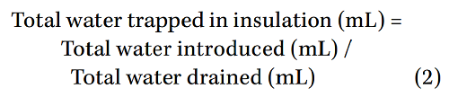
The volume(s) of drained water was recorded and used in the following equations:

For visualization of trapped moisture, the insulated assemblies were scanned at the 6 o’clock position using the backscatter radiographic technique, namely moisture detection imaging (MDI). Finally, the insulation and claddings were stripped off to visually check the condition of the pipe’s surface.
Wetting of insulation from intruding moisture is a time-dependent phenomenon and is a source of CUI. The water absorption factor of insulation under immersion conditions was measured by submerging a piece of 50 by 50 by 50-mm (2 by 2 by 2-in) mineral wool insulation in the pre-measured volume of water for a duration of 2 h, as is recommended in the applicable ASTM standard as well as previous study.10-11 The immersed insulation piece was taken out and the remaining volume of water in the jar was measured and incorporated in the following equation:
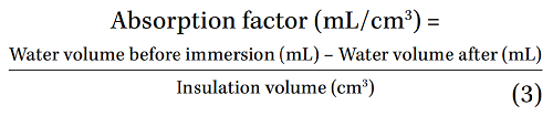
The water absorption factor of insulation from Equation (3) was incorporated in the following equation:
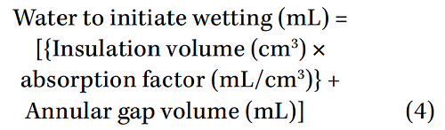
Other relative equations are:

Results and Discussion
Drainage and Wetting Behaviors
 Drainage efficiency for different insulation systems and (b) number of cycles to initiate wetting on the pipe.") Figure 3(a) shows the average drainage efficiency for insulation systems with drainage provisions after four wetting cycles, as calculated from Equation (1), whereas the calculated number of cycles to initiate pipe wetting from Equation (6) are summarized in Figure 3(b). Post-wetting MDI micrographs over each insulated system are shown in Figure 4.
Figure 3(a) shows the average drainage efficiency for insulation systems with drainage provisions after four wetting cycles, as calculated from Equation (1), whereas the calculated number of cycles to initiate pipe wetting from Equation (6) are summarized in Figure 3(b). Post-wetting MDI micrographs over each insulated system are shown in Figure 4.
It’s evident from Figures 3(a) through (b) that the contact-free insulation exhibited the highest drainage efficiency and better resistance to pipe wetting due to the least trapping of moisture during the wetting cycles. The spacers created a gap between the pipe skin (outermost diameter) and inner side of the insulation, so moisture must flood the annular gap between the pipe and insulation first before it can soak the pipe’s skin.
The presence of a perforated liner as a restrained and robust drain opening (e.g., Integrity Drain Plug†) resists the wetting by draining the water from the 6 o’clock position before it can pool and flood the annular gap between the pipe and insulation. With contacting insulations, the water droplets soak the pipe skin that, in turn, remain attached to the pipe skin due to surface tension instead of getting drained from low-point drains. Also, the drainage performance of low-point drains is subjected to variation due to the distance between drain points and moisture accumulation zone(s).
Though offset drain holes provide an eventual escape path for a portion of trapped moisture, the increased dwelling time for moisture inside the insulation increases the probability of pipe skin wetting and reduced drainage rate before the trapped moisture gets drained through the offset drain hole. The closed contacting insulation (without drain openings) will suffer cumulative wetting during each wetting cycle, making this system most vulnerable to CUI. This behavior of a closed system without drain openings is consistent with a previous study where the closed system, without drain holes in the insulation, exhibited the highest CUI and pitting.2
MDI micrographs in Figure 4 indicate the trapped moisture as bright spots within each insulated system. With an offset drain hole, significant moisture is trapped right in the vicinity of a 6-mm drain hole. Further visual inspections upon insulation removal revealed the completely dry surface of pipe after four cycles underneath contact-free insulation with the perforated liner. This further validates the result, whereas the estimated number of cycles to initiate wetting were found to be quite higher (96 Nos) in Figure 3(b) for a contact-free system.

Drain Openings Integrity
Absorbed water in the mineral wool insulation adversely impacts its thermal performance and increases the likelihood of microbiological activity. The presence of hydroxyl (OH–) groups in the cell walls of natural fibers makes them hygroscopic, thereby accommodating the moisture from the surroundings.12 Moreover, the voids between the fiber-fiber junctions or fiberbinder junction can entrap the water. Even with hydrophobic mineral wool insulations containing water repellent additives, there is a potential of moisture absorption in the event of immersion at and around the 6 o’clock position.7
In the insulated piping, as well as pipelines, operating at temperatures of ~100 °C, the moisture trapped under the insulation will be near the boiling point. This moisture may evaporate right after escaping through the drain hole (or perforated liner). Any suspended solids or salts from the evaporating moisture will deposit immediately as a loose scale or particulates inside the drain hole and over the cladding (around the drain hole). These deposits may, in turn, clog the drain opening, adversely affecting its draining capability.
Fibrous mineral wool insulations have inherent variations in thickness, up to 25%, so drilling a drain hole through an uncertain thickness of insulation increases the risk of pipe or heat tracing damage from the drill’s impact. Therefore, the use of a hardware that can keep the drain openings both in the metal cladding and fibrous mineral wool insulation aligned, and drain the moisture effectively keeping the drain hole clear and available (without any buildup or clogging), would be an effective solution.
The presence of a robust, perforated liner will resist the deformations in the drain hole that generally result from binder degradations, pipe vibrations, thermal expansions or contractions, or even from de-adhesion of insulation fibers or from external loads. With a removable-type design of these perforated liners, the clogging issue(s) can be addressed by quick removal and cleaning of liners. This eliminates the requirement of re-drilling or cleaning the clogged holes. Also, such liners can aid in the sampling of salt deposits that can remain on the perforated liners during the evaporation of drained moisture.
Finally, the self-coring design of liners made from a lower hardness material than that of CS pipe can eliminate the integrity risks encountered with drilling of the drain holes using handheld powered drill bits.
Conclusions
Four different insulated systems were tested for water trapping and drainage behaviors, followed by NDE using moisture detection imaging. The following conclusions can be derived from this experimental study:
1. A contact-free insulation system with perforated liner achieved the highest drainage efficiency and least moisture trapping due to the absence of moisture pooling at the low point and lower surface tension between the insulation and pipe.
2. Locations away from the drain openings and circumferential laps should always be inspected for moisture accumulation and corrosion.
3. A robust design for a drain opening with perforated liners can eliminate maintenance challenges that result from clogging and misalignment of unrestrained drain holes.
4. Drilling of drain openings using power drills should be avoided as it may damage the pipe and heat tracing.
Acknowledgment
The authors would like to thank Henry Frechette (Acuren, Canada) for his support with MDI radiographs.
† Trade name.
References and Author Biographies