With developments in oil and gas industries, corrosion is an integral problem and a challenge to different sections of this huge industry, both upstream and downstream. Since corrosion—a natural phenomenon— annually imposes enormous costs in different industries, especially in the oil, gas, and petrochemical industries,1 corrosion management and corrosion control are vital.
Therefore, corrosion engineers employ systems based upon economic and engineering estimations, to provide the best and most effective corrosion control methods to manage the corrosion. Simply employing different corrosion control methods (i.e., proper materials selection, cathodic protection [CP], utilization of chemical and inhibitors, etc.2) is not in turn a responsible approach to this inevitable need. Hence, corrosion monitoring as an efficient tool requires intelligent implementation of corrosion control methods or more precise evaluation of an alloy selection.
For example, NACE International SP05753 includes visual inspection of surfaces under CP, wall thickness measurements of protected vessels, surveillance of potential, and/or anodic current output as considerations in monitoring of efficient CP systems in oil-treating vessels.3
One of the oldest corrosion monitoring techniques in oil and gas industries is the corrosion coupon. In this technique for monitoring weight loss of a metallic piece made from the pipeline material in a time range, the time range depends on different parameters, especially the essence of the under-control system.
Per NACE-SP0775,4 the monitoring time is changeable depending on the intended fluid to which the coupon is exposed and the expected specific pipeline corrosion rate. Moreover, corrosion topography and surface morphology, depth of formed pits, electrolyte chemical composition, and the chemistry of sediments and corrosion products are also helpful for identifying and interpreting the system corrosivity.5-6
The NACE SP0775 standard covers preparation, installation, analysis, and interpretation of corrosion coupons in oilfield operations. Section 3.4 discusses the locations of coupons and other monitoring tools, and consideration of the most proper ones for coupons: dead fluid regions, high-velocity streams and impingement areas, downstream from points prone to possible oxygen entry, and locations where water is likely to collect in a sour system.
In this standard, there are some recommendations regarding the positioning location of corrosion coupons and/or corrosion probes in pipelines; however, there is no discussion of the access fitting installation position. Indeed, some positions of access fitting both for corrosion coupons and corrosion probes could not provide effective evaluation of the corrosion behavior of a system. For example, it is believed that the 3 o’clock position on the upstream flow lines could not effectively evaluate the actual corrosion rate of the line, especially those lines that are operated for extraction of petroleum by using the “gas lift” method.
This article is the result of several years of experience in the field of corrosion monitoring using corrosion coupons and corrosion probes, and discusses the most proper positioning of access fittings, and consequently, more intelligent monitoring of the corrosion control system. Certainly, the selection of suitable positions for access fitting installation will be enabled to gather more vital information regarding the governing process conditions and possible process upsets. Employing the presented items and utilizing the obtained data could enable one to improve interpretations, maintenance, and monitoring of the system. Hopefully, the discussions presented here will be considered by the NACE SP0775 editorial committee in the future.
Reliable Monitoring and Management
One challenge of production companies involved in well completion operations and production of oil and gas wells is sand and debris production from the reservoir formation.7 In some cases, especially in offshore wellhead facilities, process parameters show no sign of sand production, investigations, and weight-loss calculations of installed coupons demonstrating aggressive corrosion rates. This happens as everything looks normal.

Therefore, the aggressive corrosion rate is sometimes attributed to the other unknown parameters; however, the surface morphology of the corroded coupons could efficiently reveal the type of corrosion and damage. In the system with a 6 o’clock access fitting position, despite corrosion coupon/corrosion probe types or their location along the pipeline, the accumulation of associated sediments, deposits, and sands that may be present—even in the low rate fluid stream—enabled corrosion specialists to conduct a more precise estimation and more real interpretation concerning the corrosion rate calculations.
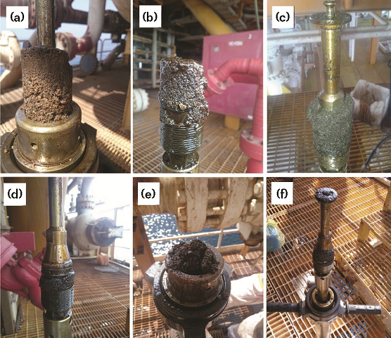
Figure 1 shows that by positioning the access fitting at 6 o’clock, regardless of the corrosion coupon type, sediments and deposits comprised of sands, grits, wax, and asphaltene gradually accumulate along the gap between the solid/ hollow plug and inside the wall of the access fitting. Obviously, coupon replacement in these conditions is associated with receiving a valuable sample including very worthwhile information.
Figure 2 depicts accumulation of these sediments with the monitoring devices set at the 6 o’clock access fitting position. Obviously, regardless of coupon type and coupon holder length, it is possible to provide and analyze a real sample of sediments and governing fluid conditions, and consequently, perform a suitable corrective action.

Avoiding Shutdowns and Mechanical Damages
These cases are important in large pipelines, and the lack of attention may leave operators and production companies confronted with pipeline shutdown. The importance of sudden and undesirable shutdown in sea lines that transport hydrocarbons was more pronounced when 1) the size of pipeline was large, 2) the position of access fitting was at 12 o’clock, and 3) the coupon was located at the 6 o’clock position utilizing a long coupon holder. This issue is more relevant and will be more important.
In some cases, this is due to distinct reasons (i.e., impingement of big pieces of disintegrated foam pigs and/or brush pigs that are accelerated by the pipeline turbulence stream) and can result in mechanical damage of the coupon holder. These mechanical damages may ultimately produce conditions where the retrieval of the coupon with coupon holder is impossible, except by complete shutdown.
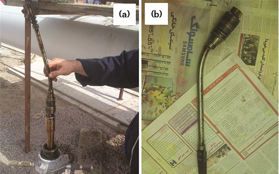
A similar case with a 3-in (7.62-cm) corrosion coupon with a 15-in (38.1-cm) coupon holder that, fortunately, could be successfully retrieved from the access fitting with the help of special arrangements and without system shutdown is shown in Figure 3. Figure 3(a) depicts the as-retrieved coupon. Figure 3(b) illustrates that the bending of the coupon holder resulted from the undesired mechanical damages. Certainly, rupturing and releasing of the end section and moving it toward the processing plant may impose serious risk to the processing plant.

If the access fitting is installed at the 6 o’clock position and the coupon is placed at 6 o’clock, the operator could retrieve the coupon, even with the occurrence of mechanical damages. Moreover, in the case of probable mechanical damages, the coupon could be retrieved more easily because of the lower curvature owing to impingement in comparison to a longer coupon holder.
It is recommended to locate the access fitting at the 6 o’clock position. Through this manner of installation, the following can be achieved: 1) avoid probable undesired shutdowns, and 2) prepare a real sample from the pipeline fluid stream to execute more reliable monitoring and management.
Disadvantages of 6 o’clock Installation
It was previously recommended to locate the access fitting at 6 o’clock, especially in transport pipelines. It is worth noting that positioning of the access fitting at 6 o’clock could be associated with some disadvantages that must be considered. In some cases, this position is not accessible. Installing the access fitting at the 6 o’clock position in systems with a fluid stream prone to sedimentation may cause some difficulties.
In these systems, accumulation of dense and compact sediments may result in lack of pressurizing of the retriever column during the first stages of opening. This can be resolved by applying a back pressure. However, the sedimentation of very dense and compact deposits is a little unexpected. It is noteworthy that this issue is not relevant and will not be problematic in the case of systems that are serviced by a hydraulic retriever.
Conclusions
In this article, the issues regarding the best position for installation of access fittings were addressed. There are some recommendations regarding the location of corrosion coupons in some documents, such as NACE SP0775; however, there is not any commendation concerning the position of access fittings. Some experiences regarding the corrosion monitoring and management were discussed and 6 o’clock was introduced as the most suitable position for the installation of access fitting assemblies.
This position can provide a real and valuable sample (sediments trapped among the access fitting and access fitting internal wall), comprising a lot of information regarding the fluid stream and process conditions. The analysis of this sample enabled the corrosion specialists to provide a more real interpretation and analysis for the rate of corrosion and corrosion conditions. This position could also avoid possible undesired shutdowns of the system, resulting from mechanical damage to the coupon holder.
However, some disadvantages of the 6 o’clock position were also mentioned (i.e., lack of pressurizing the retriever column and difficulties concerning these positions). If hydraulic accessories are accessible in a system, this position could be considered as the best position for the installation of access fittings.
References
1 FHWA-RD-01-156, “Corrosion Cost and Preventive Strategies in the United States” (Washington, DC: FHWA, 2002).
2 R.W. Revie, Uhlig's Corrosion Handbook (Hoboken, NJ: John Wiley & Sons, 2011).
3 NACE SP0575, “Internal Cathodic Protection (CP) Systems in Oil-Treating Vessels” (Houston, TX: NACE International, 2007).
4 NACE SP0775, “Preparation, Installation, Analysis, and Interpretation of Corrosion Coupons in Oilfield Operations” (Houston, TX: NACE, 2013).
5 Y. Waseda, S. Suzuki, eds., Characterization of Corrosion Products on Steel Surfaces (Berlin, Germany: Springer, 2006).
6 D.A. Jones, Principles and Prevention of Corrosion, 2nd ed. (Upper Saddle River, NY: Prentice Hall, 1996).
7 T. Ahmed, P.D. McKinney, Advanced Reservoir Engineering (Burlington, MA: Elsevier, 2005).