Corrosion imposes significant costs on the upstream oil and gas industry. One study estimates the total annual cost of corrosion to be approximately U.S. $1.4 billion.1 These costs and environmental risks are likely to rise as new hydrocarbon sources are found in more challenging environments—deeper reservoirs with higher temperatures and pressures and containing greater concentrations of acid gases.
The industry has advanced several methods to combat corrosion and extend the operating life of a well, which may be broadly classified into three main categories: 1) changing the metallurgy of the wellbore tubulars to a more expensive, higher-grade corrosion-resistant alloy (CRA), 2) chemically modifying the production fluids to reduce their intensity of corrosive attack, and 3) creating a barrier layer, such as protective coating or the injection of surfactant-based formulations that aggregate at the metal surface to block water contact and inhibit corrosion.2
The first option—upgrading to a CRA— may make sound economic sense in some instances, but is typically cost prohibitive on a large scale. Also, CRAs are sometimes subject to localized corrosion (crevice and pitting corrosion) or environmentally assisted cracking. Processing and welding these alloys can significantly influence their corrosion resistance, and thus, it is important that the final product form and manufacturing route are considered in the assessment of the suitability of the alloy for the intended operating environment. Key environmental parameters influencing the corrosion properties of CRAs include:3
• Temperature
• Chloride ion concentration
• Partial pressure of carbon dioxide (CO2)
• Partial pressure pf hydrogen sulfide (H2S)
• Environment pH
• Presence or absence of sulfur
However, while using some of the CRAs for drilling tools, it was noticed that the standard environmental conditions and material properties reported in literature and data sheets are not adequate to qualify the material for drilling tools. Failure cases reported in this article may add areas of concerns and limitations of CRAs to be considered while selecting those CRAs for similar drilling operation conditions.
Selection of Corrosion-Resistant Alloys
The selection of CRAs for producing and transporting corrosive oil and gas can be a complex procedure and, if improperly carried out, can lead to mistakes in application and misunderstanding about the performance of a CRA in a specific service environment. Table 1 includes common CRA selection procedures and their pros and cons.
Case Histories
Hydrogen-Induced Cracking of Ni-Base Alloy K-400
The armor of a cable, made of annealed nickel-copper Alloy K-400, with maximum allowable tensile strength of 550 MPa (80 ksi), and a hardness score of 87 on the Rockwell Superficial Hardness (HRB) 15-T scale,4 showed multiple cracks after six months of installation in a gas well. Cracks were observed on the section where the armor (and the cable) was not immersed in the well fluid. Armor immersed in the fluid was free from cracks. The presence of 4.2% sodium chloride (NaCl), 5 ppm H2S, and 5% of CO2 were reported.
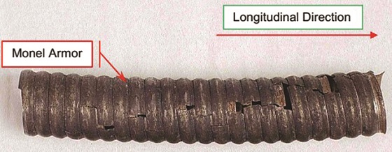
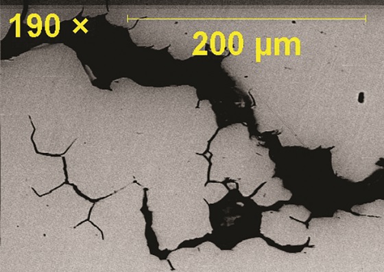
The as-received section of Alloy K-400 armor showed numerous cracks propagating in the longitudinal direction on the entire section (Figure 1). Cracks were mostly intergranular in nature (Figure 2). Corrosion pits were also evident on both interior and outside diameter surfaces, indicating exposure to an aggressive acidic environment.
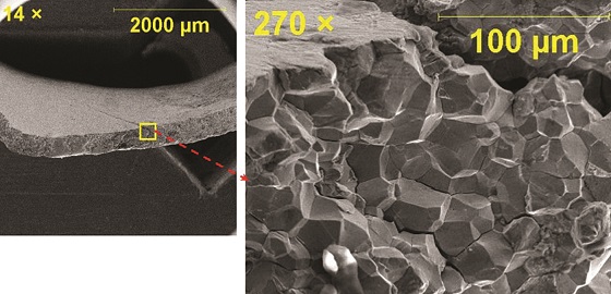
The cleaned fractured surface was examined under scanning electron microscopy (SEM). The fractograph (Figure 3) showed a “rock candy” appearance, which is usually observed when the grain structure is equiaxed, confirmed intergranular fracture. Also, few intergranular secondary cracks were observed, which indicate the possibility of hydrogen-induced cracking (HIC) (Figure 3). Measured hardness was within the range of 95 to 98 HRB scale, which is higher than the maximum allowable value (87 HR 15-T or 81 HRB) of the armor material. Semiquantitative chemical analysis of the fractured surface, using energy-dispersive x-ray spectroscopy, identified the presence of sulfur, which is likely due to exposure of the armor material to an H2S environment.
Sodium halide brine was used as the completion fluid. The formation of mineral scales on the armor surface also confirm the possibility of mixing incompatible waters. When CRAs are simultaneously exposed to a common gas (such as oxygen [O2], CO2, or H2S) and halide brine, then pitting and stress corrosion cracking are likely to occur. This is the primary reason naturally passivating, anti-oxidizing formate brines are being widely used. In the current case, it is suspected that the failure might be due to condensation of liberated acid gas (H2S, CO2, etc.) coming from the well.
A previous study showed that Alloy K-400 is susceptible to pitting, where chlorides penetrate the passive film. The presence of sulfides, H2S, and CO2 enhances pitting corrosion, and systematically impairs the resistance criteria for this type of attack. The presence of H2S is likely to poison the hydrogen recombination reaction (that would ordinarily occur) and force the hydrogen atom to enter the metal structure rather than bubble off from the corroding surface. Thus, the HIC of the armor might have occurred due to the synergistic effect of chloride content, CO2, H2S, and a low pH of the fluid condensed on the surface of the armor. NACE standard MR0175/ISO 151565 states, “Some combinations of the values of temperature, H2S, chloride, and pH may not be acceptable for cracking resistance of Alloy K-400.”
Microbiologically Influenced Corrosion of Alloy 718
Microbiologically influenced corrosion (MIC) is a form of corrosion caused by living organisms, such as bacteria, algae, or fungi and often associated with the presence of tubercles or slimy organic substances.6 Of these, bacteria make up the greatest portion of both the biomass and total nucleic acid on the planet by far.7 Microorganisms excrete waste products that are called metabolites. Polymeric metabolites form the biofilm matrix. At the fluid/metal interface, biofilm-free areas are different from biofilm-covered areas. This results in an electropotential gradient at the metal surface resulting in an anode-cathode reaction.
A field location in the United States reported failure of a drilling tool pressure compensator at a depth of 3,460 m. The tool assembly shares a single compensator system utilizing a bellows assembly. Visual examination identified multiple pinholes on convolutes of the bellows, which caused mud invasion to the turbine and flooding of the tool. The bellows assembly is free to move axially within the housing. The exterior is exposed to oil, and the interior to mud. Drilling mud used during this operation was water-based with a pH of 9.5. The construction material of the bellows assembly was Alloy 718, per Aerospace Material Specification AMS 5596K.8
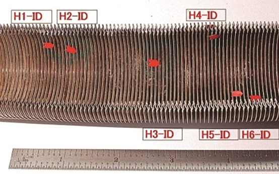
Six visible pinholes were randomly distributed on the submitted bellows sample (Figure 4). All the pinholes were located on the convolutes. SEM examination (Figure 5) also revealed signs of tuberculation and tunneling at the periphery of the underlying pinhole, suggesting the occurrence of MIC. The presence of a high content of sulfur in corrosion products supported the likelihood of sulfate-reducing bacteria responsible for MIC.
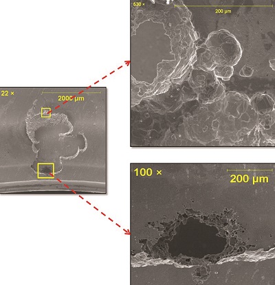 Since the failure of the bellows was observed after 40 min of the operation, pinhole formation is unlikely to occur in such a short period. Therefore, it is highly suspected that corrosion might have initiated before the job, during storage, where MIC-causing bacteria might have entered, along with contaminated water used for washing the bellows.
Conclusions
• The construction material Alloy K-400/500 meets the requirement of NACE MR0175/ISO 15156; however, field failures restricted the use of these alloys to a H2S maximum partial pressure of 3.45 kPa (0.50 psi) and a minimum pH of 4.5, when NACE MR0175 was published in 2003. As field failures have been reported below the H2S partial pressure and pH values set by NACE MR0175, selection criteria of these alloys at aggressive sour environments should be further reviewed.
• More test results are necessary for better understanding of pitting corrosion behavior of Alloy 718 in downhole and MIC conditions and to help engineers in selecting this material for microbially contaminated environments.
• When using high-strength Alloy 718 (yield strength MPa 1,035 [150 ksi]), application of properly heat-treated material (free from Nb-rich phases) should be ensured.
• When selecting Alloy 718, welded areas must be properly post weld heat treated (PWHT) to avoid Nb-rich phase segregation. If highly controlled PWHT could not be applied, due to size or configuration restrictions of the part, then a low heat input/high cooling rate welding technique, such as electron-beam (E-Beam) welding, may be considered. The small heat affected zone of the E-Beam welded area may not adversely affect the strength of the component.
References
1 G.H. Koch, et al., “Corrosion Costs and Preventive Strategies in the United States,” Report by CC Technologies Laboratories, Inc. to Federal Highway Administration (FHWA), Office of Infrastructure Research and Development, FHWA-RD-01-156, January 2001.
2 K. Nalli, “Corrosion and Its Mitigation in the Oil and Gas Industry—An Overview,” Petromin Pipeliner 13 (2010).
3 B.D. Craig, L. Smith, “Corrosion Resistant Alloys (CRAs) in the Oil and Gas Industry— Selection Guidelines Update,” Nickel Institute Technical, 10 073, 3 (2011).
4 ASTM E18-19, “Standard Test Methods for Rockwell Hardness of Metallic Materials” (West Conshohocken, PA: ASTM International, 2018).
5 NACE MR0175/ISO 15156, “Sulfide Stress Corrosion Resistant Metallic Materials for Oilfield Equipment” (Houston, TX: NACE International).
6 B. Little, et al., “Microbiologically Influenced Corrosion of Corrosion Resistance Materials,” Proceedings of Tri-Service Conference on Corrosion, held June 21-23, 1994 (Orlando, FL: Government Printing House, 1994).
7 M. Madigan, J. Martinko, J. Parker, Brock, Biology of Microorganisms, 10th ed. (Upper Saddle River, NJ: Prentice Hall, 2003), p. 6.
8 SAE International AMS 5596K, “Nickel Alloy, Corrosion and Heat-Resistant, Sheet, Strip, Foil and Plate 52.5Ni - 19Cr - 3.0Mo - 5.1Cb (Nb) - 0.90Ti - 0.50Al - 18Fe Consumable Electrode Remelted or Vacuum Induction Melted 1775 °F (968 °C) Solution Heat Treated” (Warrendale, PA: SAE International, 2012).