Many factors can play a role in early degradation of concrete power poles, including damage from corrosion and mechanical forces. Corrosive agents and water penetrate through the soil into the buried part of the concrete pole. This can produce a wicking effect where the penetrating groundwater begins to evaporate after reaching a height above the atmospheric-buried interface of the pole. This leads to an increase in concentration of corrosive agents in the lower part of the pole and the occurrence of color changes in this location. The wicking ultimately leads to reinforcement corrosion and as a result, cracking and spalling of the concrete cover.1
The weight of electrical cables attached to the pole and wind forces can bend the pole. These loads can produce cracks in the concrete in both atmospheric and buried portions. These cracks can accelerate the penetration of corrosive agents into concrete and as a result, accelerate degradation of the pole.
In some cases, moisture, air pollution, and corrosion of the concrete poles in the lower part can result in conditions of leaking electrical current from the high-voltage electrical wires through the insulators, to the concrete pole, and then to the ground, which accelerates degradation of the pole.1-4
 H cross section, and (b) round cross section or O section.") As shown in Figure 1, there are two different types of concrete power poles typically constructed in Iran. The first type has a round section (O poles) and the second has an H-shaped section (H poles). The O poles are prestressed, so they exhibit less bending vs. the cable weight and wind force. Also, a centrifugal method is used in their construction, so centrifugal force helps remove excess water from the concrete prior to curing. Thus, a high-strength, low-permeability concrete with a minimum water-to-cement ratio is formed. The poles have high durability in normal environmental exposure and therefore there is not a mechanical degradation problem in using them in Iran. In contrast to the O poles, the H poles employ a low-quality concrete, have low durability in environmental exposure, and after about five years, concrete degradation is visible in the lower part of the pole through color change of the concrete. To resolve this deleterious situation, the following modifications were made in the H poles:
As shown in Figure 1, there are two different types of concrete power poles typically constructed in Iran. The first type has a round section (O poles) and the second has an H-shaped section (H poles). The O poles are prestressed, so they exhibit less bending vs. the cable weight and wind force. Also, a centrifugal method is used in their construction, so centrifugal force helps remove excess water from the concrete prior to curing. Thus, a high-strength, low-permeability concrete with a minimum water-to-cement ratio is formed. The poles have high durability in normal environmental exposure and therefore there is not a mechanical degradation problem in using them in Iran. In contrast to the O poles, the H poles employ a low-quality concrete, have low durability in environmental exposure, and after about five years, concrete degradation is visible in the lower part of the pole through color change of the concrete. To resolve this deleterious situation, the following modifications were made in the H poles:
1. Use superplasticizer for reducing the water-to-cement ratio of the mix and increase the concrete strength.
2. Add silica fume as a super pozzolan material in the concrete mix design to reduce concrete permeability.
3. Increase the thickness of concrete cover over the rebar in the lower part of the H pole by converting the H cross section in the lower part to a cube cross section.
4. Apply epoxy-glass fiber coating in the slightly higher and lower part of the buried atmospheric zone to prevent the accumulation of corrosive agent and color changes from groundwater.
Changing the line of production of the H pole so that it can produce prestressed H concrete poles came with a considerable expense. Although it was a good serviceability proposal, it was not accepted due to financial considerations.
Results and Discussion
Aggregate Tests
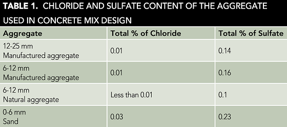
The aggregates and water commonly used in preparing the concrete used for the H poles were investigated in terms of the amounts of corrosive agents, including chloride and sulfate. The chloride content of water was measured according to ASTM D1411-09,5 and was 40 ppm. Based on ASTM D512-12,6 the maximum permitted chloride content of water for use in new concrete is 1,000 ppm, so the typical mix water was within the permitted limit. Also, the chloride and sulfate content of aggregates were measured according to the gravimetric method. Their values are shown in Table 1. Based on the Iran Concrete Regulation,7 they were less than the maximum allowed content, which are 0.4 and 0.04% for chloride and sulfate, respectively.
Sand equivalent (SE) value is another important factor that was considered and investigated. If SE value is low, it means there is a significant amount of particles <75 µm in the sand. Often these are clays that can cover the aggregate surface, thereby preventing sufficient adhesion of cement gel to the surface of the aggregate during the curing process. This reduces concrete strength and increases its permeability. The SE value was measured according to ASSHTO T176.8 It was 73; therefore, it wasn’t suitable for application in the concrete mix design. The sand was washed with water to remove the clay particles and the SE value increased to 86.
In addition, if concrete aggregates are reactive to the alkaline environment produced during curing, it subsequently can produce an expansive silica gel in the presence of moisture. The expansive gel produces an internal pressure within the concrete that creates surface cracks. This is called the alkali silica reaction (ASR) problem.
ASR is a chemical reaction between different active amorphous silica minerals of aggregate and the alkali pore solution of concrete. This reaction produces a dark gel around the aggregate that has high activity for the reaction with moisture and water. When the gel adsorbs moisture, it expands and produces cracks in concrete.9 When ASR starts in concrete, it generally can’t be controlled. ASR cracks facilitate penetration of corrosive agents, like chloride or carbon dioxide (CO2), into concrete that can initiate corrosion at the concrete-rebar interface. Like the ASR gel, the corrosion products are expansive and accelerate crack growth and spalling that further expose the embedded rebar to corrosion.
 Another reason for concrete pole cracks is delayed ettringite formation (DEF). Ettringite is normally produced in early cement hydration. If the curing temperature is above 70 to 80 °C, formation of ettringite mineral is prevented.9 For acceleration of curing, the concrete poles generally are cured in heated water vapor, so they can develop a DEF condition. After several years, and in lower parts of a concrete pole in contact with water or moisture, ettringite can be formed. Its formation is accompanied by expansion and can cause concrete cracks. Like ASR, DEF cracks accelerate penetration of corrosion agents, like chloride or CO2, into the concrete and increase corrosion of rebar and spalling of the concrete cover.
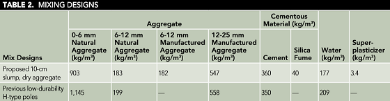
The aggregate used for manufacturing the H poles was tested for ASR according to ASTM C289-03.10 According to Figure 2, the concrete aggregate was in a low-risk area of the ASTM C289 curve and the aggregates did not exhibit an ASR problem. Another effective factor in the formation of high-strength concrete is the use of a dense grade of aggregate. Particle size analysis was done on the aggregate and a proposed concrete mix design is shown in Table 2. Table 2 also includes the concrete mix design, which was used previously for unmodified power poles.
Concrete Test
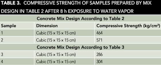
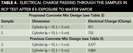
After making the changes as discussed previously, concrete samples were constructed in accordance to the proposed concrete mix design mentioned in Table 2. Further, some samples were prepared according to the previous mix design (Table 2). The samples were cured for 28 days in water at 25 °C. Compressive strength and rapid chloride permeability (RCP) tests were performed on them. In most cases, the higher the compressive strength of concrete, the longer the concrete durability when exposed to environmental conditions, with greater concrete density and lower permeability to corrosive agents. However, the RCP test was performed to confirm the increase in durability and decrease in permeability. According to Tables 3 and 4, concrete samples with modified mix design had considerably higher compressive and lower electrical charge than the others. Concrete poles that have been constructed by the new mix design will have longer durability than the previous unmodified concrete pole in environmental conditions.
Concrete Power Pole Test
To ensure quality of the concrete poles, some of them were subjected to a bending test like that described in CEB Standard 044-3.11
A comparison of results of the bending test of modified poles with the previous unmodified poles showed that the modified poles had better acceptance bending behavior in the test, so it is reasonable to expect it would have greater durability when exposed to environmental conditions. The details and results of this testing will be presented in a subsequent paper.
Conclusion
Mechanical and corrosion factors are involved in the early degradation of concrete H poles. Therefore, improvements that increase mechanical strength of the H poles and application of methods that reduce the penetration of corrosive agents in the buried zone of H poles, such as applying epoxy-glass coating, reduce the permeability of concrete and increase the durability of concrete poles under environmental conditions.
References
1 A. Aghajani, M.A. Golozar, A. Saatchi, et al., “Stray Alternating Current and Environmental Effects on Concrete Power Poles,” MP 52, 8 (2013).
2 A. Aghajani, M.A. Golozar, A. Saatchi, et al., “Stray Alternating Current Problems in Concrete Power Poles,” MP 52, 5 (2013).
3 A. Aghajani, M.A. Golozar, A. Saatchi, et al., “Protecting Concrete Power Poles from Stray Alternating Current,” MP 52, 10 (2013).
4 A. Aghajani, M. Urgen, “Effects of Highly Polluted Atmospheres on Power Distribution Systems,” MP 53, 12 (2014).
5 ASTM D1411-09, “Standard Test Methods for Water-Soluble Chlorides Present as Admixtures in Graded Aggregate Road Mixes” (West Conshohocken, PA: ASTM International, 2009).
6 ASTM D512-12, “Standard Test Methods for Chloride Ion in Water” (West Conshohocken, PA: ASTM, 2012).
7 Iran Concrete Regulation, Publication of Management and Planning Organization of Iran (2000).
8 AASHTO T176-08, “Standard Method of Test for Plastic Fines in Graded Aggregates and Soils by Use of the Sand Equivalent Test” (Washington, DC: American Association of State and Highway Transportation Officials, 2017).
9 L. Bertolini, B. Elsener, P. Pedeferri, et al., Corrosion of Steel in Concrete, 1st ed. (Weinheim, Germany: Wiley-VCH Verlag GmbH & Co. KGaA, 2004).
10 ASTM C289-03, “Standard Test Method for Potential Alkali-Silica Reactivity of Aggregates” (West Conshohocken, PA: ASTM, 2003).
11 CEB Standard 044-3, “Specification for Acceptance Test of Concrete Poles” (Colombo, Sri Lanka: Ceylon Electricity Board, 1966).