Editor’s note: Learn more about corrosion of stainless steel (SS) in this new Materials Performance quarterly special feature, “The Science Behind It.” Read the following MP article about the root cause of a Type 316L SS closed drain line failure, then explore the science behind the corrosion problem, which is presented in several related CORROSION articles listed at the end of the article.
Pipes made of Type 316L austenitic stainless steel (SS) (UNS S31603) were used for water drain lines in a gas separator plant operated by an oil and gas production drain line at the 4 o’clock position after only four months in service. A small hydrocarbon pool formed under the leak. The nominal outer diameter and wall thickness of the pipe were 101.6 mm and 6.8 mm, respectively. The process conditions were 380 °C flow temperature, 320 KPa pressure, 1,998.5 kg/h mass flow, and 2 m/h flow rate. A small section, 250 mm in length, was cut from the spool containing the leak to conduct investigations into the root cause of this early failure.
Investigation Methodology
The pipe was visually examined in the as-received condition (Figure 1). The sample was then subjected to nondestructive examinations, including dye penetrant testing for cracks and ultrasonic testing (UT) for thickness measurements. The pipe also was cut and sectioned for destructive tests. Chemical analysis of the pipe material was carried out using spark-ignition spectroscopy. Macro- and microstructure investigations were conducted for specimens close to and remote from the failure site.
Mechanical grinding with 1200-grade emery paper was followed by polishing with a 0.1-µm agglomerated alpha alumina suspension, rinsing and degreasing with acetone, and finally electro-etching with 10% oxalic acid (C2H2O4) at 6 V for 45 s. Scanning electron microscopy (SEM), equipped with energy dispersive spectroscopy (EDS) analysis, was used for in-depth examination of the damaged section and existing phases. Hardness measurements were made in various areas under a load of 10 kg for 15 s.
Results
Spark-ignition spectroscopy showed the following chemical composition for the pipe: 0.02% C, 0.36% Si, 1.44% Mn, 0.025% P, 0.01% S, 16.5% Cr, 2.02% Mo, 12.39% Ni, 0.32% Cu, and the balance Fe, which conforms to the specifications for ASTM A358316L.1 General and close-up views of the damaged section from both the outer and inner surfaces are shown in Figures 1 and 2, respectively. The most relevant observation is that the as-received pipe has two localized damage zones, located at about 4 and 8 o’clock, which are just below the line indicating the typical air/liquid interface on the inner surface (Figure 2).
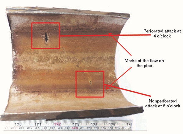
One of these resulted in a perforation while the other penetrated half of the pipe wall thickness, indicating that the localized attack was initiated from the inner surface. No localized attack or mechanical damage was observed on other parts of the received failed pipe. Additionally, no corrosion products were seen on the inner surfaces of the pipe; and no localized thinning of the wall was detected elsewhere by UT. Dye penetrant testing on the inner surfaces revealed no surface cracks in either the damaged or undamaged zones.
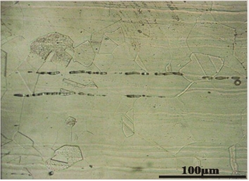
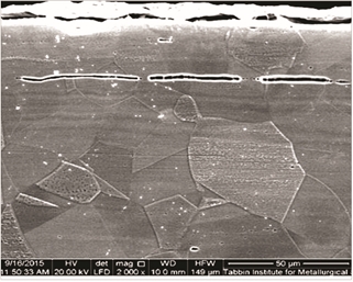
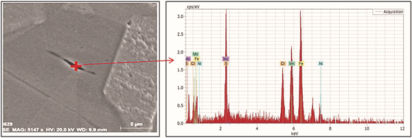
The optical microstructure of the pipe material was found to have austenitic grains with numerous twins, elongated inclusions in the rolling direction of the steel plates, and remaining deformation bands, which are seen in Figure 3. SEM images of the pipe microstructure at different locations show typical austenitic grains with elongated nonmetallic inclusions and deformation bands (Figure 4). EDS spot analysis was carried out on an elongated inclusion and the results are shown in Figure 5.
 |  |
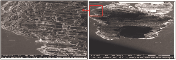
These results show unusually high percentages of manganese and sulfur, indicating the presence of manganese sulfide (MnS) inclusions in the matrix of pipe material with the following composition: 42.2% Fe, 23.41% Mn, 13.75% Cr, 12.8% S, 6.66% Ni, and 1.18% Mo. SEM images of localized damage at the cross section of the damage zone (in the rolling direction of the pipe plate) are shown in Figure 6. Shear bands are more visible at the cross section of the corroded portion of the metal. The figure also shows the localized corrosion damaged in the rolling direction.
Hardness values (Vickers) obtained for the pipe material were ~180 HV. This hardness value of the pipe is slightly higher than the value of solution annealing (~160 HV). This may be attributed to the presence of remaining shear bands related to the plate deformation. The results of hardness measurements are in good agreement with the investigated microstructures.
Discussion
A general visual examination of the received segment of pipe showed that the localized damage was limited to two locations, namely at 4 and 8 o’ clock just below the liquid line (Figure 2); and that no other type of damage occurred elsewhere in the received pipe.
Nondestructive examination using dye penetrant and UT measurements supported the visual observations and excluded the presence of surface cracks, reduction in wall thickness, or any other type of damage. Chemical analysis by spark- ignition spectroscopy showed the pipe material conformed to the chemical composition specified by ASTM A358-316L.
Microstructure investigations, SEM images, EDS analysis, and hardness measurements indicated the presence of nonmetallic MnS inclusions and residual shear bands related to the pipe manufacturing process (cold deformation).
According to the results obtained, failure of this segment of pipe could be attributed to differential aeration or liquid-line corrosion, especially occurring when the pipe was drained, as reflected in the damage at both 4 and 8 o’clock locations below the water line. This water line attack is a type of localized corrosion related to a differential aeration cell, where corrosion attack is below the water line and within a distance representing the limit of soluble oxygen in the flowing fluid. The higher oxygen solubility zone acts as the cathode while the area below acts as the anode where localized corrosion takes place.
In addition, the presence of dispersed inclusions, mainly MnS, in the pipe material resulted in the formation of localized galvanic cells within the anodic zone at both the 4 and 8 o’clock locations. Here, MnS inclusions represented very small concentrated anodes, which led to complete dissolution of the MnS and perforation of the pipe.
In addition, the presence of residual shear bands, related to cold deformation during pipe manufacturing, intensified the localized corrosion damage. Cold deformation is recognized for producing a reduction in the corrosion resistance of the material. The accepted localized corrosion mechanism explains that the deterioration effect of shear bands associated with cold deformation is related to the additional energy in the metal. Consequently, the thermodynamic durability of the material is decreased.
Conclusions
Based on this investigation, the root cause of the failure of the received segment of pipe is attributable primarily to waterline corrosion in combination with the material defects (MnS inclusions) and residual shear bands produced during pipe manufacturing. These defects, in the presence of residual solution after pipe drainage, resulted in the formation of localized galvanic corrosion cells that further concentrated corrosion at the MnS inclusions, which acted as very small anodic areas. The consequences were complete dissolution and failure.
Recommendations
It is recommended to use better quality pipe material within the same grade, and to inspect it prior to installation to verify that the material is free from inclusions and shear bands. Preferably, operating conditions would keep the piping completely filled with water to the extent possible and minimize periods of line drainage. This would reduce the effects of the differential aeration corrosion cells associated with the air/liquid interface. The practicality of applying internal cathodic protection should also be investigated.
Acknowledgment
The financial support of the Central Metallurgical Research & Development Institute and Ministry of Petroleum are acknowledged.
Reference
1 ASTM A358/A358M-08a, “Standard Specification for Electric-Fusion-Welded Austenitic Chromium-Nickel Stainless Steel Pipe for High-Temperature Service and General Applications” (West Conshohocken, PA: ASTM International, 2008).
Bibliography
Corrosion: Fundamentals, Testing, and Protection. ASM Handbook, Vol. 13. Materials Park, OH: ASM International, 2003.
Eklund, G.S. “Initiation of Pitting at Sulfide Inclusions in Stainless Steel.” J. of the Electrochemical Society 121 (1974): p. 467.
Kumar B.R., B. Mahato, R. Singh. “Influence of Cold Worked Structure on Electrochemical Properties of Austenitic Stainless Steels.” Metallurgical and Materials Transactions 38A (2007): p. 2,085.
Peguet, L., B. Malki, B. Baroux. “Influence of Cold Working on the Pitting Corrosion Resistance of Stainless Steels.” Corros. Sci. 49, 4 (2007): pp. 1,933-1,948.
Rutkowska-Gorczyca, M., M. Podrez-Radziszewska, J. Kajtoch. “Influence of Cold Working Process on the Corrosion Resistance of Steel 316L.” SIM XXXVII, Kraków-Krynica (2009): p. 319.
Surowska, B., A. Weronski. “Cold Work Effect of Pitting Corrosion of Some Biomaterials.” Proc. of the 14th International Scientific Conference on Advanced Materials and Technologies, held May 17-25, 1995. GliwiceZakopane, Poland, p. 425.
Zhilin, L., L. Wei, Q. Juncai. “The Effect of Electrochemically Induced Annealing on the Pitting Resistance of Metastable Austenitic Stainless Steel.” Metallurgical and Materials Transactions 37A, 2 (2006): p. 435.
Zor S., M. Soncu, L. Capan. “Corrosion Behavior of G-X CrNiMoNb 18-10 Austenitic Stainless Steel in Acidic Solutions.” J. of Alloys and Compounds 480 (2009): p. 885.
S.A. KHODIR is a researcher at Central Metallurgical Research and Development Institute (CMRDI), El-Tebbin, Helwan, 11421, Cairo, Egypt, e-mail: saadkhodir@cmrdi.sci.eg. He works as a researcher in CMRDI, with qualifications as follows: expertise in hydrogen embrittlement of high strength steel alloys; a lecturer in welding training courses for Egyptian, Arabian, and African engineers; a lecturer in the international welding engineers courses for Egyptian engineers; surface modifications of alloys by welding and thermal spray processes; friction stir welding of metals; surface modifications of alloys by welding and thermal spray processes; and failure case analysis of boilers and structural steels.
H. ABDEL-ALEEM is a researcher at CMRDI, e-mail: hamedaa@gmail.com. He works as a researcher in CMRDI with qualifications as follow: a lecturer in the training welding courses for Egyptian, Arabian, and African engineers; a lecturer in the international welding engineers courses for Egyptian engineers; surface modifications of alloys by welding and thermal spray processes; nondestructive testing of steel weldments; and failure case analysis of boilers and structural steels.