Protective coating is one of the most effective methodologies for protecting pipelines from corrosive environments. Protective coatings have excellent physical and chemical resistance that provide adequate protection with a useful life. As a result of recent developments in protective coatings, fusion-bonded epoxy (FBE) coating has been utilized to provide internal protection against corrosion in a sour gas pipeline.1-2
Liquid epoxies have also been utilized to coat internal girth welds, while FBE coatings have been used to coat the surface pipe.2-3 Corrosion protection requires that good adhesion properties are achieved between the substrate and coating. The safety and operation of pipelines are also dependent on the coating’s quality and performance.4 Common gas pipeline requirements in the designed allowance include the ability to launch and retrieve pigs for cleaning and inspection activities. These pigs are designed to remove water, sediment, wax, and other debris. Low adherence coatings or improperly applied coatings are often removed or damaged by pig launching and receiving. During a recent launch of a pig, failed coating pieces were received having different colors.3 Therefore, it is critical to determine the fundamental causes behind several coating failures. A comprehensive test program was developed to determine the possible causes of the premature FBE internal coating failure.5
A key property to the success of FBE coating is an adequate curing or intercoat crosslinking. At the appropriate application temperature, proper formation of coatings includes complete curing. The appropriate level of curing is generally determined by the glass transition temperature.5 If the coating is exposed to service before complete curing, it can result in premature failure where the properties of the coating are not fully developed. Additionally, when the coating further cures through chemical reaction under increased operating temperatures, shrinkage stresses develop, resulting in debonding of the coating. Reports showed that a low glass transition temperature (Tg) compared to the reference sample or a nonfailing sample is a clear indication of lack of cure. More curing leads to a coating with a higher Tg.4
Experimental Investigation
Various techniques were utilized to investigate the root cause of the failure of the FBE coating, including Fourier transform infrared (FTIR), differential scanning calorimetric (DSC), and thermogravimetric analyzer (TGA).
Results and Discussion
 and failed (A, B, and D) coating.")
Fourier Transform Infrared
FTIR spectroscopy was used to determine the type and the chemical structure of the coating to compare it with the fingerprint of the same type of coating usually applied to flowlines. An FTIR technique was utilized to obtain the chemical constituents of the coating samples. FTIR spectra were recorded by using FTIR equipped with Golden Gate† within a wave number measurement range of 500 to 4,000 cm−1. Three failed coating samples and a control coating sample were analyzed with FTIR to determine whether the coatings are identical. Coating degradation can be indicated by analyzing and comparing the coating’s chemical structure peaks of failed samples with a control coating system.5-12
 and failed (C).")
The FTIR results showed that the compositions of the failed coating samples (A, B, and D) were comparable with reference A (control), as shown in Figure 1, while sample C had a similar profile (composition) with reference C (control), as shown in Figure 2. Some similarities were observed as well as some structural differences, as highlighted in Figure 3, where the FTIR results of reference samples A and C are presented. The results indicate that the source of all failed coating samples came only from two types of coating systems (A and C), where three failed coating samples were attributed to sample A (control), body coating system, and one failed sample was attributed to sample C (control), girth weld coating system.
9
Samples A and control A, B, and D have the same epoxy chemical structures and with a probable combination of 3, 4-epoxycyclohexyl-3’4’-epoxycyclohexane carboxylate (ECC) and diglycidyl ether of bisphenol-A (DGEBA) based. ECC is one of the most common cycloaliphatic epoxy structures in a six-member aliphatic cycle, shifting its absorptions in the mid-range toward lower wave numbers, so the main oxirane absorption for this structure is located ~799 cm−1 and for DGEBA structures at 827 cm−1. A part of the oxirane absorptions ECC resin shows that the bands are corresponding to the C=O stretching (1,730 cm−1) of esters.
 and reference (C).")
Control samples A and C have some structural differences and it seems that control sample C has mainly glycidyl end capped poly(bisphenol-A-co-epichlorohydrin) based epoxide structure. The assignments for this structure are as follows: 3,700 to 3,300 cm−1 to O-H group, the N-H stretching occurs near 3,300 cm−1 but cannot be clearly discerned due to the broad hydroxyl region, 2,930 to 2,860 cm−1 to the CH3, CH2, and CH stretching. Peaks at 1,240 and 1,181 cm−1 were due to the presence of -C-C-O-C- stretching.
Thermogravimetric Analyzer
A TGA was used for measuring the weight losses and loss on ignition of the samples. TGA was adjusted from ambient temperature to 600 °C at the rate of 20 °C/ min and under air. Figure 4 shows the TGA results of all coating samples, reference and failed.6 The TGA results are also consistent with the results obtained from FTIR. The TGA results clearly show that the reference material (sample A, control) results are similar to the failed sample profiles (A, B, and D). Also, the TGA result of failed sample C was comparable to reference C.
The results show that both reference C and failed sample C had less thermal stability and more weight loss than reference A and failed samples (A, B, and D), supporting FTIR results for structural differences with other samples. The TGA results indicate that the beige failed coating sample (B) showed the worst performance in the TGA experiment, where the degree of degradation is proportionally correlated to the thermal stability. It is also worth mentioning that the reference coating system A (control) exhibited the best thermal performance.
 and reference (C) coating samples.")
Differential Scanning Calorimetric
DSC was carried out to investigate the curing of FBE coating. The DSC temperatures were adjusted as follows (in accordance with Canadian Standard CSA Z245.20 Series 10—Plant-applied external coatings for steel pipe7,10):
1. Run 1: Heating the same sample from 25 to 110 °C at a rate of 20 °C/min, held at 110 °C for 2 min, and then cooled immediately to 25 °C.
2. Run 2: Heating the same sample from 25 to 300 °C at a rate of 20 °C/min, and then cooled immediately to 25 °C.
3. Run 3: Heating the same sample from 25 to 140 °C at a rate of 20 °C/min.
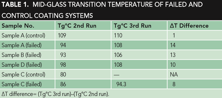
Table 1 shows the Tg of the second and third DSC run of the reference coating systems A (control) and C, in addition to the failed coating samples.
The DSC third run results show that the Tg of the reference coating material sample A (control) was similar to the Tg of the failed samples (A, B, and D), as shown in Table 1. The obvious difference in the Tg of the DSC is the second and third run of filmed samples A, B, and D, which revealed that the materials had not been fully cured, while the Tg of the second and third run of the reference coating system sample A (control) were almost comparable, indicating that the coating material had been fully cured, as shown in Table 1. The second run is more related to the degree of curing, while the third run is more related to the type of coating system. This improper curing could be a key factor of the coating failure. The improper curing is also observed in the failed sample C (yellow), where an obvious difference was indicated in the Tg of the DSC second and third run. Different parameters, like crosslink density (curing differences), chemical and compositional differences, thickness, aging and exposure to different chemicals, application parameters (temperature, humidity, etc.), and surface preparation should also be considered.
Conclusion
A failure study was conducted on failed internal coating samples collected during the scraping of a gas pipeline. The investigative study was based on FTIR, TGA, and DSC of the collected failed samples and compared to reference coatings. The results clearly showed that the failed body and girth weld coating samples came from two different types of coating systems. The inadequate curing of the failed coating samples could be a key factor in this coating failure.
† Trade name.
References
1 A. Groysman, Corrosion Problems and Solutions in Oil Refining and Petrochemical Industry (Basel, Switzerland: Springer International Publishing, 2017).
2 A.U. Malik, et al., “Corrosion and Mechanical Behavior of Fusion Bonded Epoxy (FBE) in Aqueous Media,” Desalination 150, 3 (2002): pp. 247-254.
3 C. Smith, et al., “Coatings for Corrosion Protection: Offshore Oil and Gas Operation Facilities, Marine Pipeline, and Ship Structures,” NIST Special Publication, 1035, April 14-16, 2004: pp. 132-143.
4 D.G. Weldon, “Failure Analysis and Degree of Cure,” J. Prot. Coatings Linings 22 (2005): pp. 48-55.
5 C. Smith, et al., “Coatings for Corrosion Protection: Offshore Oil and Gas Operation
Facilities, Marine Pipeline, and Ship Structures,” NIST Special Publication, 1035, April 14-16, 2004: pp. 178-201.
6 A. Husain, et al., “Investigation on the Failure of Fusion Bonded Powder Epoxy Internal Coating of a Production Flow Line from an Oil Exploration in Kuwait—A Case Study,” Sixth International Conference on Engineering Failure Analysis, paper no. ICEFAV1 (Lisbon, Portugal: Engineering Failure Analysis, 2014).
7 A. Husain, et al., “Differential Scanning Calorimetry and Optical Photo Microscopy Examination for the Analysis of Failure of Fusion Bonded Powder Epoxy Internal Coating,” Engineering Failure Analysis 56 (2014): pp. 375-383.
8 S. Luo, et al., “Effect of Curing Degree and Fillers on Slurry Erosion Behavior of Fusion-Bonded Epoxy Powder Coatings,” Wear 254, 3-4 (2003): pp. 292-297.
9 A. Husain, J. Chakkamalayath, S. Al-Bahar, “Electrochemical Impedance Spectroscopy as a Rapid Technique for Evaluating the Failure of Fusion Bonded Epoxy Powder Coating,” Engineering Failure Analysis 82 (2017): pp. 765-775.
10 CSA Z245.20, “External Fusion Bond Epoxy Coating of Steel Pipe” (Ottawa, ON: Standards Council of Canada, 2006).
11 G.T. Bayer, M. Zamanzadeh, “Failure Analysis of Paints and Coatings” (Pittsburgh, PA: Matco Associates, Inc., 2004).
12 F. Deflorian, L. Fedrizzi, P.L. Bonora, “Corrosion Behaviour of Epoxy Coated Galvanized Steel,” in Progress in the Understanding and Prevention of Corrosion 1, eds. J.M. Costa, A.D. Mercer (London, U.K.: The Institute of Materials, 1993), p. 215.