Ammonium chloride (NH4Cl) corrosion is primarily known to occur in overhead condensers, tower trays, interconnected piping, and heat exchangers of crude units. It happens wherever nitrogen and chlorides are present.1-15 These contaminants can become a part of the crude oil feedstock in several ways: raw crude, slop oil, and desalter water. Hydrolysis of metal chlorides in the crude leads to the formation of hydrochloric acid (HCl).11
Chlorides carried downstream of crude units lead to NH4Cl corrosion in overheads and pump-arounds associated with hydroprocessing, catalytic reforming, fluidized catalytic cracking, and coker units. Neutralizers, such as ammonia (NH3) and organic amines, are routinely utilized in overhead systems for chloride control and to mitigate against acidic conditions. This is a delicate task, and prone to misapplication, since underdosing leads to acid corrosion, while overdosing causes localized, underdeposit corrosion when NH4Cl, or amine-HCl, precipitates before or above the water dew point.
NH4Cl is hygroscopic and can precipitate when NH3 and HCl are in vapor form, with salt hydration possible even above the water dew point (>300 °F [149 °C]). Another path for salt formation is dissolution of acid and base in water, followed by boiling the solution dry. The temperature at which a salt first precipitates is called the “salt point” and deposition occurs when the molar partial pressure product of NH3 and HCl is greater than the NH4Cl stability constant.1,3,6
Initially, small salt particles do not accumulate, but are carried away with the gas stream. However, at larger particle sizes, enough water is absorbed by the deposits to cause aggressive localized attack (>100 mpy). Hence, absorption of a small amount of water is sufficient to cause damage under “boil-dry” conditions. This has been validated by relative humidity (RH) measurements performed experimentally, where a RH value of 20% was needed for general corrosion of carbon steel (CS).14 At a critical RH value (60%), severe corrosion was observed. Above 65% RH, corrosion rates decreased. Hence, salt deposition occurring after or below the water dew point is not an issue since the salt dissolves away or is not formed at all due to the reduction of reactant concentration in the vapor through dissolution in water. NH4Cl is considered an acid salt, and corrosion inhibitors are not effective.8,13 NH4Cl formation also leads to fouling and plugging, causing pressure drops and loss of throughput.
Ionic equilibria modeling (IEM) has been successfully used to determine system pH and salt formation tendencies to help choose appropriate neutralizers that can target both acid corrosion and underdeposit corrosion.3-4,12 Corrosion modeling to predict corrosion rates has also been undertaken by researchers and validated with lab data.13 However, field application of models has been less effective due to the unique and complex chemistries in affected systems. Also, it is very challenging to detect chemical constituents in process streams in time to respond effectively.
Tackling this corrosion mechanism from both process and materials perspectives requires a multi-pronged approach.5-10,12-13 Minimizing water entrainment and chloride sources in hydrocarbon streams, along with temperature control through better design, can optimize the process. However, if NH4Cl precipitation is unavoidable, then water washing is installed at appropriate upstream injection points. Computational fluid dynamics have been utilized to optimize wash water injection schedules.9 In practice, the volume of water injected is always above what is needed to achieve water condensation at the injection point. If excess water is not made available, there can be situations where incomplete dissolution of the salt occurs. This could lead to the formation of dilute, corrosive solutions downstream of injection points upon local salt redeposition.
All commonly used materials are susceptible as described in API 57116 with CS being the most susceptible and titanium (Ti) being most resistant. Within the potential-pH regimes under which NH4Cl corrosion operates, the Cl- ion has enough driving force to prevent oxygen adsorption on the steel surface at an atomic level.15 This interferes with the repassivating ability, especially for stainless steels (SS) and corrosion-resistant alloys (CRAs). Additionally, upgrading from CS to Alloy 825 or duplex SS can shift the damage mechanism from underdeposit corrosion to chloride stress corrosion cracking.2,5 Depending on the turnaround time and budget constraints, decisions can be made on upgrading to higher nickel alloys (or using a cladding thereof), which can mitigate NH4Cl corrosion to a large extent, but does not imply immunity.
In this article, case histories from two refineries describing the rapid, localized and unpredictable nature of NH4Cl corrosion are presented. Best practice mitigation strategies are proposed as well.
Case Studies on NH4Cl Corrosion
Case History 1—Overhead Piping Failure in Crude Tower at Refinery A
Following a through wall failure of the overhead piping on a crude tower, a thermodynamic survey of the process environment, and a metallurgical analysis of a pipe ring collected from the failure location were carried out. The results indicated that corrosive salts forming in the system were directly responsible for equipment damage and eventual failure.
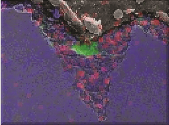
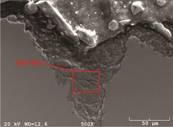
A pipe ring cut from the CS overhead line immediately upstream of the failure was removed and analyzed (Figure 1). Cross sections were prepared for metallography, scanning electron microscopy (SEM), and energy dispersive x-ray spectrometry (EDS). Figures 2 and 3 show the localized nature of the pits. The intensity of the color in the EDS map represents the relative concentration of elements within the pit (green = chlorides). In addition to the preferential attack along the pipe bottom and the presence of chlorides in the scale, the damage profile was consistent with a flowing, corrosive media attacking the metal surface. The operating temperature at this location was too hot for water to condense, leaving only corrosive salts as possible aggressors.
Ion chromatography performed on deposits collected from various locations in the overhead line helped identify the anions and cations in the environment. The pH was between 3.2¬¬¬¬¬–3.5. Chlorides were predominant (10,000 to 40,000 ppm), while amine composition was primarily methylmonoethanolamine (4,000 to 8,000 ppm) and methyldiethanolamine (MDEA) (10,000 to 30,000 ppm). NH3 (~200 ppm) was also present. The presence of acidic components and chlorides in the salt indicates that corrosive acid salts were formed (product of strong acids and weak bases) when chlorides reacted with NH3 and various amines trafficking through the process vapor. The presence of MDEA was alarming, since it can decompose in a furnace environment to produce monoethanolamine, which is an aggressive salt former. Large losses of MDEA from the amine treating facilities had been reported. However, from the solids analysis it was not possible to determine which base made the salt first. Once a salt forms, it constitutes a new phase in the system, and all other ionic species in the surrounding environment establish an equilibrium with the salt. Since the deposit is acidic, it readily reacts with bases in the vapor phase, and these compounds become part of the deposit composition. The only way to sort these reactions and determine original salt deposit contributors is IEM.
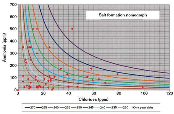
IEM indicated that the unit operation was vastly improved over previous years, but still not within a safe operating envelope. Salt formation nomographs of NH3 levels in the overhead vapor with increasing chloride contents were plotted for system temperatures (230 to 270 °F [110 to 132 °C]) over a period of one year (Figure 4). NH4Cl salts were found to be forming at temperatures greater than system temperatures exiting the heat exchangers, thereby causing localized corrosion of the overhead line.
This refinery had a history of corrosion failures resulting in overhead line replacement multiple times. Although a materials upgrade would have mitigated this corrosion mechanism, it could not be implemented since construction of Ti piping is not common. Improved process control and monitoring were the only options. Hence, continued IEM and water analysis, wash water optimization, and corrosion monitoring were recommended. Insulation was applied to this line to prevent condensation that could cause corrosion. IEM revealed that corrosive salts were forming due to the NH3 in the process. New simulations helped better adjust contaminant levels. Also, significant pH depression in the condensing water of the exchangers (pH <1) was noted, implying loss of neutralizer and an unreliable neutralizer injection system. Shortcomings in the water wash design were also found, and a new design was recommended upstream of the planned water wash location.
Case History 2—Overhead Line Failure in Crude Unit at Refinery B
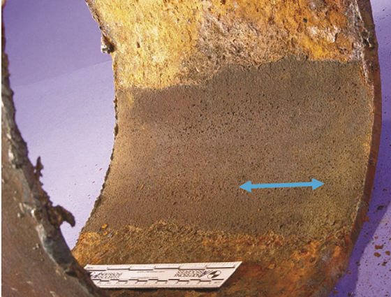
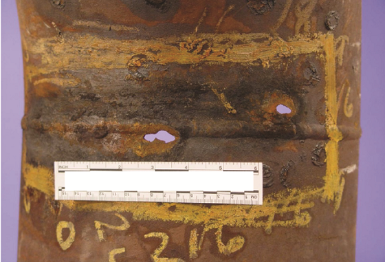
Refinery B suffered an overhead line failure on its crude unit atmospheric tower. A pipe section from the CS line was submitted for failure analysis. Corrosion was observed on the inner diameter (ID) only, with a strip of protected metal along the pipe bottom (Figure 5, blue arrows). The through wall failures appeared to be grouped around a weld line (Figure 6). The ID was coated with flaky scale throughout the area of attack. X-ray fluorescence indicated that the scale contained 45% chlorides and 35% oxides, consistent with salt deposits rather than aqueous acid corrosion. Also, acid attack does not leave such a scale accumulation at the point of greatest activity. The uncorroded section along the pipe bottom also testifies to pH buffered water flowing in this area and not acidic media.
Although this unit had a water wash system installed with proper distribution equipment, its location was not at an optimal spot. The presence of the uncorroded surface along the pipe bottom was evidence that pH control was maintained by neutralizer application practice at the time. However, the water wash was inadequate in reducing contaminant levels sufficiently to prevent salt formation downstream. The location for water injection was several feet upstream of the pipe elbow at the bottom of the vertical run of pipe coming down the tower. This site left very little time for the distributed spray from the nozzle to interact with the vapor before the directional change collapsed the spray pattern into a stream along the bottom. Hence, two recommendations were made: perform an ionic modeling study of the system to confirm system velocities and proper wash water requirements, and move the water injection site to the top of the tower, spraying down from the second elbow to allow maximum contact time between the spray droplets and the process vapor.
Mitigation Strategies to Counter NH4Cl Corrosion
Improved corrosion management can be achieved through operational and process control. Contaminant levels in the overhead fluctuate over a wide range, thereby posing a huge challenge to corrosion mitigation and unit reliability. Upgrading materials from CS to CRAs is an option, but is cost prohibitive. Higher corrosion allowances may increase service life but will not reduce corrosion rates. Hence, the following strategies can be adopted:
1. IEM can be utilized to estimate pH and temperatures at the aqueous dew point, and determine deposit composition. Key inputs are overhead accumulator water and desalter wash water analyses. This helps identify “tramp” amines and choose the most effective neutralizers.
2. Optimize water washing so that salt-forming constituents are absorbed in water prior to the advent of NH4Cl forming conditions. However, dissolving salts is the only practical approach. Since salts form in areas inaccessible to wash droplets, proper design and location of injection points are important factors to allow maximum contact time between the spray droplets and the process vapor. Poorly designed systems lead to inadequate water being available to dissolve away these salts, causing the corrosion mechanism to shift to downstream units.
3. Accurate temperature profile measurement using infrared guns or cameras enables better determination of the water dew point and salt formation point.
4. Corrosion rate and thickness monitoring tools, such as an internal rotary inspection system, ultrasonic thickness, or x-ray methods, can be placed at susceptible locations and wall thickness tracked frequently (two to three times annually), especially at areas around the most recent failure. Electrical resistance probes and weight loss coupons should also be considered. Nonintrusive techniques (hydrogen permeation probes) can be used for real-time monitoring.
This article is based on CORROSION 2017 paper no. 9574, presented in New Orleans, Louisiana, USA.
References
1 Y.-M. Wu, “Calculations Estimate Process Stream Descriptions,” Oil & Gas J. 91, 1 (1994).
2 A.J. Bagdasarian, D.J. Truax, “Chloride Stress Corrosion Cracking of Austenitic Stainless Steels in Hydroprocessing Units,” CORROSION/97, paper no. 501 (Houston, TX: NACE International, 1997).
3 V.K. Braden, P.R. Petersen, “Crude Unit Overhead Corrosion Control,” CORROSION/98, paper no. 585 (Houston, TX: NACE, 1998).
4 G.G. Duggan, R.G. Rechtien, “Application of Ionic Equilibria Process Simulation for Atmospheric Distillation Overhead Systems,” CORROSION/98, paper no. 586 (Houston, TX: NACE, 1998).
5 A. Singh, C. Harvey, “Corrosion Management in Fractionator Feed Preheat Exchangers in Hydroprocessing Units,” CORROSION 2000, paper no. 00687 (Houston, TX: NACE, 2000).
6 J.R. Rue, J.G. Edmondson, “Control of SaltInitiated Corrosion in Crude Unit Overhead Systems,” CORROSION 2001, paper no. 01538 (Houston, TX: NACE, 2001).
7 P.R. Petersen, et al., “Impact of Ammonium Chloride Salt Deposition on Refinery Operations,” CORROSION 2001, paper no. 01540 (Houston, TX: NACE, 2001).
8 C. Shargay, et al., “Design Considerations to Minimize Ammonium Chloride Corrosion in Hydrotreater REAC’s,” CORROSION 2001, paper no. 01543 (Houston, TX: NACE, 2001).
9 K. Toba, et al., “A New Approach to Prevent Corrosion of the Reactor Effluent System in HDS Units,” CORROSION 2003, paper no. 03653 (Houston, TX: NACE, 2003).
10 R. Rechtien, G. Duggan, “Identifying the Impacts of Amine Contamination on Crude Units,” CORROSION 2006, paper no. 06581 (Houston, TX: NACE, 2006).
11 NACE Publication 34109, “Crude Distillation Unit—Distillation Tower Overhead System” (Houston, TX: NACE, 2009).
12 G. Duggan, et al., “Multiple Corrosion Mechanisms in a Crude Distillation Overhead System,” CORROSION 2009, paper no. 09332 (Houston, TX: NACE, 2009).
13 A. Sun, D. Fan, “Prediction, Monitoring and Control of Ammonium Chloride Corrosion in Refining Processes,” CORROSION/2010, paper no. 10359 (Houston, TX: NACE, 2010).
14 K. Toba, et al., “Corrosion of Carbon Steel and Alloys in Ammonium Chloride Salt,” CORROSION 2014, paper no. 4007 (Houston, TX: NACE, 2014).
15 C.D. Taylor, “Modeling Corrosion, Atom by Atom,” Interface (Pennington, NJ: The Electrochemical Society, Winter 2014).
16 API 571, “Damage Mechanisms Affecting Fixed Equipment in the Refining Industry” (Washington, DC: American Petroleum Institute, 2011).