Ingenuity, creativity, and resourcefulness are characteristics that corrosion engineers inherently embody due to the nature of their work in the field. One project that required out-of-the-box thinking was the evaluation of the condition of the 70-year-old pipelines carrying treated effluent water into San Francisco Bay. After several engineering firms reviewed the project, they felt an assessment of the pipes was not possible and therefore recommended a prohibitively expensive replacement of the pipes.
However, with novel and unconventional techniques, the engineers of JDH Corrosion Consultants (Concord, California, USA) were able to accurately determine the degree of corrosion on both the inside of the pipes as well as on the exterior of the pipelines and as a result were able to save the City of San Francisco millions of dollars by avoiding unnecessary pipeline replacement.

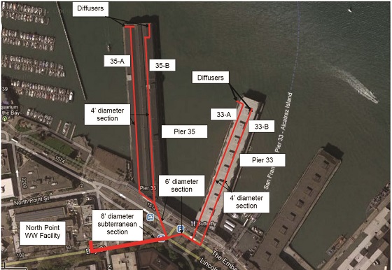
The City of San Francisco’s North Point Facility (NPF) treats effluent from a nearby wastewater plant, and sends it through four outfall pipelines, called the North Point Outfall (NPO), where it empties into the San Francisco Bay. The NPF treats up to 135 to 150 million gallons of wastewater per day. That wastewater arrives at the NPF Dechlorination Building, where it is treated. The treated water then travels downstream over a weir, and through a closed-channel conduit. Next, it flows through a concrete sewer, which is 8 ft (2.4 m) in diameter. That sewer then encounters a junction where it splits into two reinforced sewers that are 6 ft (1.8 m) in diameter, with one sending water toward Pier 33, and the other toward Pier 35.
Before reaching the seawall, each of the two pipes meets another junction and each pipe divides again into two reinforced concrete sewers (4 ft [1.2 m] in diameter) under San Francisco’s famous Embarcadero. Underneath Pier 33 and Pier 35, these four pipes (two under each pier) transition into cast iron pipes. They are suspended underneath the pier, extend out ~1,000 ft (300 m), and then drop down to the floor of the bay. In the 1970s, regulatory requirements mandated that four diffuser pipes (85 ft [25 m] long) be added to encourage dilution. Steel beams attached to the pier structural piles support the diffusers. See Figure 1 for a schematic of the NPO. See Figure 2 for a satellite view of Pier 33 and Pier 35.
Ideally, the city was hoping the infrastructure could be used for another 30 to 50 years, but they needed to determine the condition of the pipelines and their support structures and whether they were fit to continue operating, needed repairs or replacements, or required coating or lining repair. However, several engineering firms expressed that these pipelines couldn’t be properly evaluated and, instead, must be replaced, which would cost millions of dollars.
Ultimately, JDH Corrosion Consultants, Inc. was awarded the contract and they concluded the pipelines could, indeed, be evaluated. According to J. Darby Howard, Jr., who is a principal engineer and president of the company and a member of NACE International, “We saw the report and we said, ‘No! We can go down there. We can use a Zodiac [boat] to access the pipelines and we’ve got the testing techniques that will allow us to evaluate these old cast iron pipelines.’ And we did it.”
The investigation involved several different phases, which included a visual external inspection of the NPO; a visual internal inspection of the NPO pipes; an ultrasonic thickness (UT) measurement of the NPO pipes; a visual inspection of the support structures; cathodic protection (CP) testing; delamination testing; phenolphthalein testing; and an investigation of the ductile iron diffuser. The entire evaluation took approximately four months. “It was quite a while because we had to go in at different stages on different pipes,” says Howard. “We had to coordinate with divers. Then, we had to figure out different ways to get our raft in the water. It was an extensive project.”
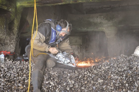
The visual external inspections took place on each pipe based on the visual condition of the coating, such as rust stains, cracking, and delamination. In order to thoroughly inspect the cast iron pipe, the marine growth and mortar coating had to first be removed. Once removed, the inspectors noticed a light layer of graphite. Graphite occurs when the cast iron lines corrode and iron leaches out of the metal, leaving a graphite matrix behind. Interestingly, the graphite appears to have protected the pipe by creating a second layer of coating, protecting it from further corrosion.
“When we typically look at metals in seawater, there’s a certain corrosion rate that we anticipate,” says Howard. “But it looked to us like the combination of barnacles, plus the graphite that formed, actually seemed to slow down the corrosion process. We expected a much greater degree of corrosion than we actually found. That’s why you’ve got to go out and look at these things. Sometimes they surprise you, in even the worst environment possible—a splash zone in San Francisco Bay—we still didn’t get as high corrosion rates as we anticipated.” Upon inspection, the team discovered minimal pitting and found the pipes to be in satisfactory condition externally.
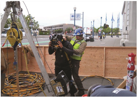
To inspect the pipes internally, a diving team was brought in. This was a critical step in obtaining a thorough evaluation and enabled the team to find trouble spots and further evaluate those spots using UT testing. Additionally, the divers identified sediment and debris levels, the degree of corrosion, pipe joint gap distances, and the general condition of the interior pipelines. They wore full dive gear, plus video cameras, which allowed the crew to view their progress (Figure 3).
While the divers were inside the pipe, the facility had to be shut down. Because the pipes were open to the bay, the amount of water in the pipes was tidally influenced. “Without water, they’re kind of crawling with all this gear on and it weighs a lot,” says Howard. “But when you get water in the pipe they said then, ‘We can kind of swim down and it takes the weight off.’ So, from the diver’s standpoint, they actually enjoyed doing the inspection when there was more water in the pipe, rather than when it was dry because it was a lot less strenuous.”
While the divers identified corroded areas on the interior of the pipe, a signal transmitter allowed the crew to pinpoint their exact location on the exterior and perform UT testing. Figuring out a method to perform UT testing with a guaranteed high degree of accuracy was an interesting puzzle to solve. A calibration block was needed to ensure accurate readings; however, the cast iron was quite old and no calibration block was available in that for this exact metallurgy.
According to Howard, “Cast iron is not like regular carbon steel, it’s not as uniform. And because of the way cast iron is produced, it may have flakes or nodules inside the metal itself.” This made the collection of precise UT reading all the more important. Fortunately, a creative solution was reached. An abandoned pipe existed under one of the piers, which was the same age as the pipes being tested. The city allowed a section of that pipe to be removed, and from it a calibration block was created (Figure 4). The UT tests concluded that the outfall pipelines had an average thickness of >1.45 in (36.8 mm), categorizing them as Class B. The pressure ratings for Class B pipelines greatly exceeds the maximum operating pressure for these pipelines.
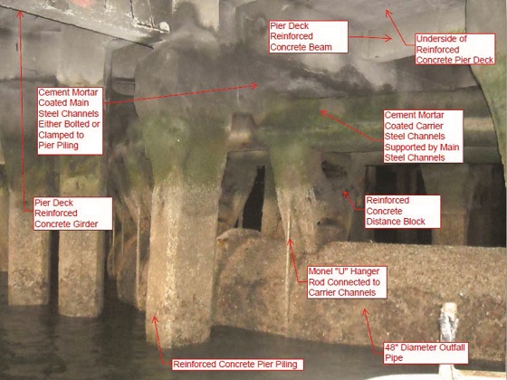
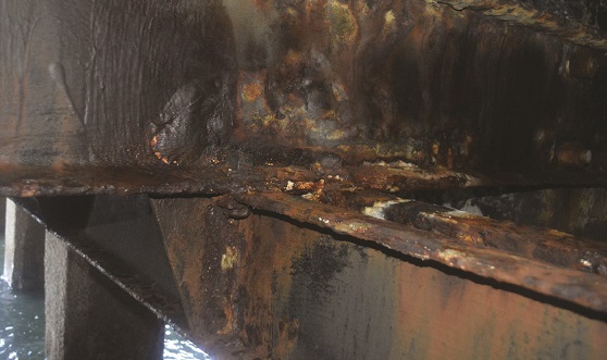
Several additional tests were performed. A pipeline electrical continuity and CP current requirement test indicated that the pipe was electrically continuous and ~20 A of CP would be enough to adequately protect each pipeline. A visual inspection was performed on the support structure, which consisted of hanger rods, distance blocks, longitudinal beams, and transverse beams (Figure 5). The hanger rods appeared to be in excellent condition, and the distance blocks were in good condition. Evidence of corrosion was found on the transverse beams due to failure of the concrete coating, which had been penetrated by seawater. The longitudinal beams were found to be in similar condition. The team concluded that a great deal of structural integrity remained and recommended that the epoxy and concrete coatings be repaired.
A delamination test was completed on both the mortar coating and the concrete coating of the support structures and a phenolphthalein test was done to determine whether the concrete was carbonated or not and identify the pH value of the concrete. Finally, a visual inspection, a UT test, and a continuity test of the ductile iron diffusers took place. Divers noted a buildup of silt and sand in the bottom of the diffusers, but based on the data obtained, the diffusers were deemed to be in satisfactory condition. The recommendation was made to add CP to extend their life an additional 30 years.
Amazingly, given the age of the NPO, none of the areas inspected and tested indicated any evidence of significant metal loss. Because of this, it was determined that a new structural liner was not needed, and instead, a nonstructural liner would be adequate. Applying CP to the pipelines and ductile iron diffusers via aluminum anodes (Figure 6) was also suggested. Howard confirmed that all recommendations have been implemented and the NPO is expected to run another 30 to 50 years. JDH has a longterm contract with the City of San Francisco to annually inspect the system, ensure it is functioning properly, and gather data to help trend the corrosion of the anodes.
Howard notes that working under the piers in a raft included some challenges, such as waves created by passing ferries or oil tankers, which could be over 2 ft (0.61 m) high, or startling the occasional unsuspecting sea lion. He admits, though, that it was a bonus for him and the team to work right next to Pier 39, one of the nation’s famous tourist attractions. “When you finish your work, you walk over to the pier where there’s all these great restaurants. We get to float around under the piers and then go have a great meal afterward. So you know what? It’s a cool job!”
This article is based on CORROSION 2019 paper no. 12832, presented in Nashville, Tennessee, USA.